Hybrid drive apparatus and controller for hybrid drive apparatus

Inactive Publication Date: 2012-06-07
TOYOTA JIDOSHA KK +1
View PDF12 Cites 36 Cited by
  • Summary
  • Abstract
  • Description
  • Claims
  • Application Information

AI Technical Summary

Benefits of technology

[0013]The present invention provides a hybrid drive apparatus that prevents excessive battery consumption and that allows a power transmission mechanism to be lubricated when a vehicle

Problems solved by technology

However, in a case where the motor generator is kept driven while the vehicle travels in the motor drive mode (EV drive mode), this causes the amount of battery consumed by the motor generator to excessively increase.
This can possibly cause some problems, such as reducing a traveling distance of the vehicle in the EV drive mode.
It results in minimizing the amount of battery consumed by the m

Method used


Image

  • Hybrid drive apparatus and controller for hybrid drive apparatus
  • Hybrid drive apparatus and controller for hybrid drive apparatus
  • Hybrid drive apparatus and controller for hybrid drive apparatus

Examples


first embodiment

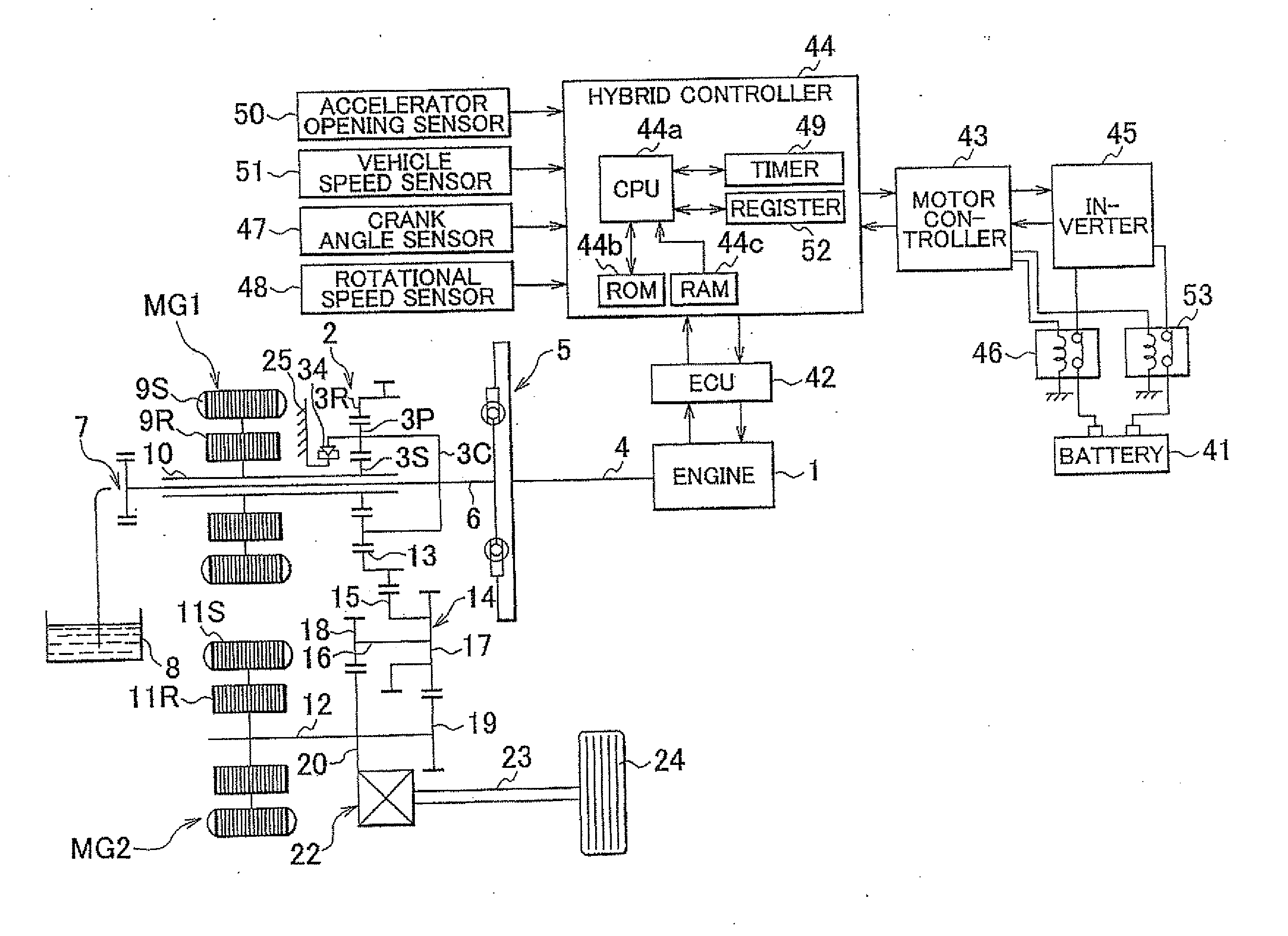
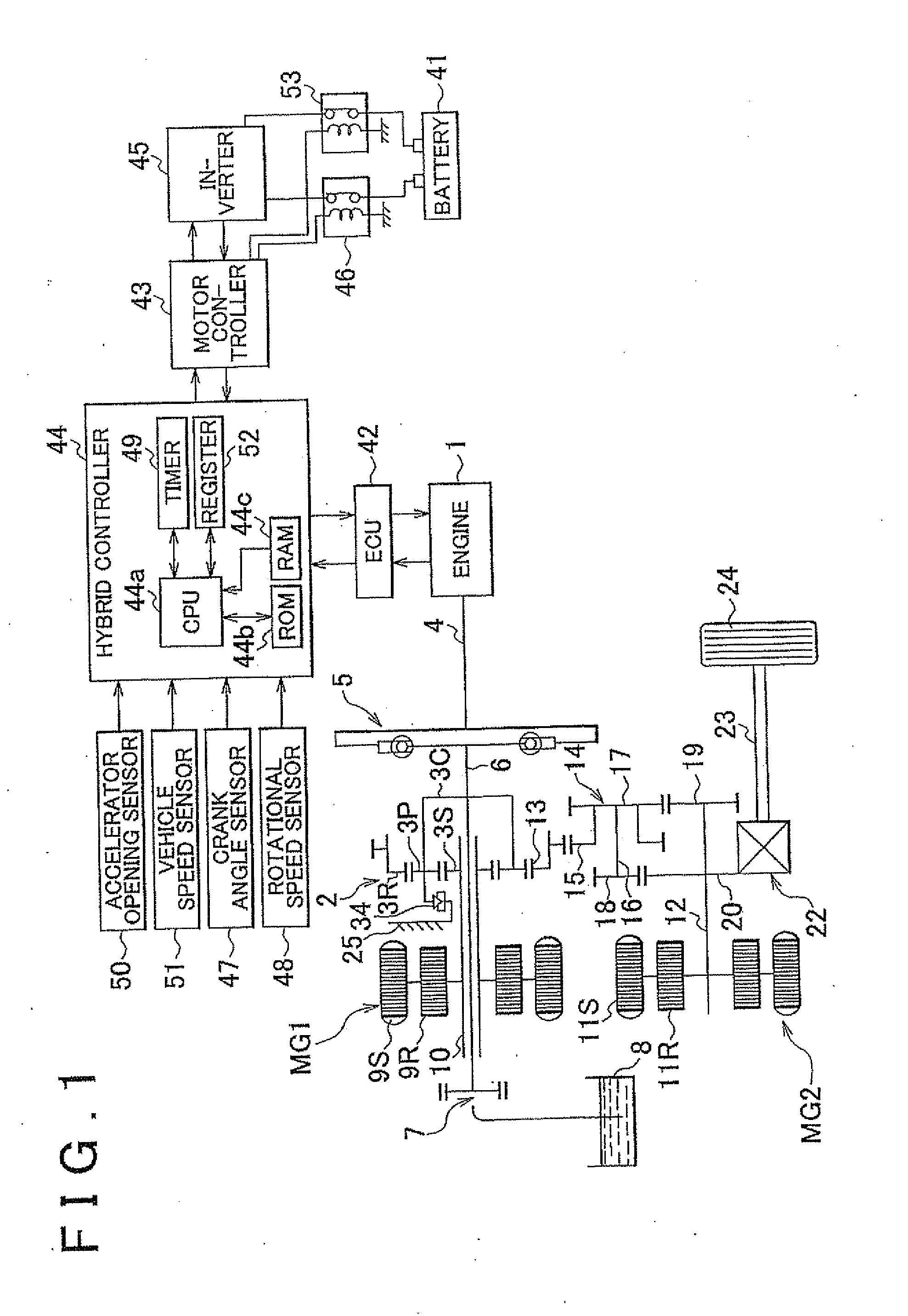
[0033]FIG. 1 to FIG. 6 illustrate a hybrid drive apparatus and a controller for the hybrid drive apparatus according to the first embodiment of the present invention.

[0034]A configuration of the hybrid drive apparatus and the controller for the hybrid drive apparatus will be first described. In FIG. 1, a transaxle serves as the hybrid drive apparatus and includes a motor generator MG1, a motor generator MG2, and a transfer gearbox (power transmission mechanism) 2. The motor generator MG1 converts kinetic energy of an engine 1, which serves as an internal combustion engine, into electrical energy. The motor generator MG2 serves as an auxiliary drive power source for the engine 1. The transfer gearbox 2 distributes an output of the engine 1 to two systems, that is, the motor generator MG1 and drive wheels 24. The engine 1, the motor generator MG1, and the motor generator MG2 form the drive power source. The motor generator MG1 serves as a first electric motor, while the motor generato...

second embodiment

[0118]FIG. 7 illustrates the hybrid drive apparatus and the controller for the hybrid drive apparatus according to a second embodiment of the present invention. In the following description, like numerals denote like elements among the first and second embodiments, and the description of the like elements is not repeated.

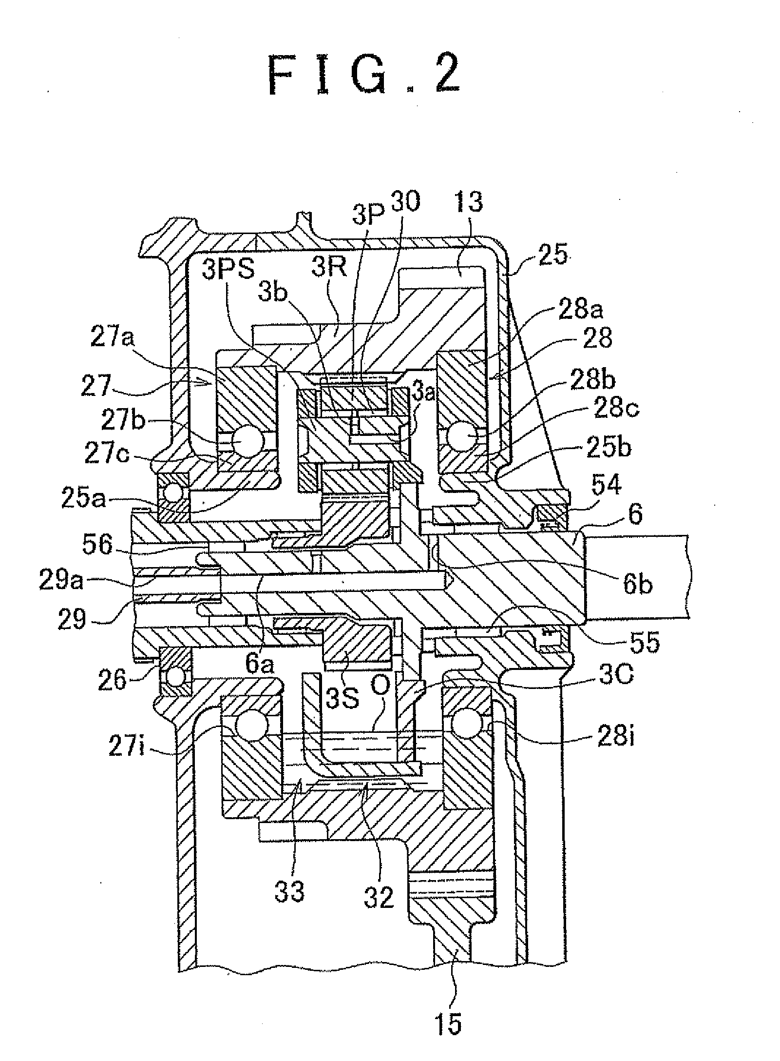
[0119]In FIG. 7, annular members 61a and 61b are provided respectively between the ring gear 3R and the outer race 27a of the ball bearing 27 and between the ring gear 3R and the outer race 28a of the ball bearing 28. The annular members 61a and 61b have their respective ends on outerside in the radial direction (radially outer ends). The radially outer ends are pressed into gaps respectively between the outer race 27a and an inner peripheral step portion 62a of the ring gear 3R and between the outer race 28a and an inner peripheral step portion 62b of the ring gear 3R.

[0120]The annular members 61a and 61b are designed respectively to cover a part of a gap between t...

third embodiment

[0122]FIG. 8 and FIG. 9 illustrate the hybrid drive apparatus and the controller for the hybrid drive apparatus according to a third embodiment of the present invention. In the following description, like numerals denote like elements among the first to third embodiments, and the description of the like elements is not repeated.

[0123]In FIG. 8 and FIG. 9, plural discharge holes 71a and 71b are formed between the annular support portion 25b of the case 25 and the inner race 28c of the ball bearing 28. The discharge holes 71a and 71b are designed to discharge part of the oil flowing from the oil reservoir 33. The discharge holes 71a and 71b each are a slot formed on a part of a circumference of the annular support portion 25b.

[0124]The ball bearing 28 has one end in the axial direction (one radial end). The case 25 has a wall surface 25c. Between the one axial end and the wall surface 25c, an oil discharge passage 72 is formed to communicate with the discharge hole 71b (an oil discha...


PUM


Abstract

A hybrid drive apparatus includes: a drive power source that includes an internal combustion engine, a first electric motor, and a second electric motor; a power transmission mechanism that includes a carrier, a sun gear, and a ring gear, and that is configured to rotate the output shaft of the internal combustion engine by the first electric motor; and plural bearings that each includes an outer ring member and an inner ring member fitted to the outer ring member through a rolling element, and that are provided apart from each other in an axial direction of the output shaft with the carrier being positioned between the bearings. An inner periphery of the outer ring member is positioned more inward in a radial direction of the ring gear relative to a meshing portion between inner teeth of the ring gear and outer teeth of one of the pinion gears.

Description

INCORPORATION BY REFERENCE[0001]The disclosure of Japanese Patent Application No. 2010-271655 filed on Dec. 6, 2010 including the specification, drawings and abstract is incorporated herein by reference in its entirety.BACKGROUND OF THE INVENTION[0002]1. Field of the Invention[0003]The present invention relates to a hybrid drive apparatus and a controller for the hybrid drive apparatus. More particularly, the present invention relates to a hybrid drive apparatus that is configured to allow a vehicle to use only an electric motor as a drive power source to travel in motor drive mode when rotational driving of an internal combustion engine is stopped, and relates to a controller for the hybrid drive apparatus.[0004]2. Description of Related Art[0005]Conventionally-known hybrid vehicles use an internal combustion engine and a motor generator (an electric motor) as a drive power source to rotate an output shaft of the internal combustion engine. The rotations of the output shaft activat...

Claims


Application Information

Patent Timeline
IPC IPC(8): F16H3/72B60W20/00B60L50/16
CPCF16H2200/2005F16H2200/2082F16H57/0484B60K6/40Y10T477/26F16H57/045Y02T10/6239B60K6/445F16H57/0457F16H2037/0866Y02T10/62
Inventor KITAHATA, TAKESHIOBATA, TATSUOKUWAHARA, TAKESHIKIMURA, HIROMICHISAITO, TORUTANAE, MASAHIRO
Owner TOYOTA JIDOSHA KK
Why Eureka
Try Eureka