Anomaly detector of permanent magnet synchronous electric motor
- Summary
- Abstract
- Description
- Claims
- Application Information
AI Technical Summary
Benefits of technology
Problems solved by technology
Method used
Image
Examples
first embodiment
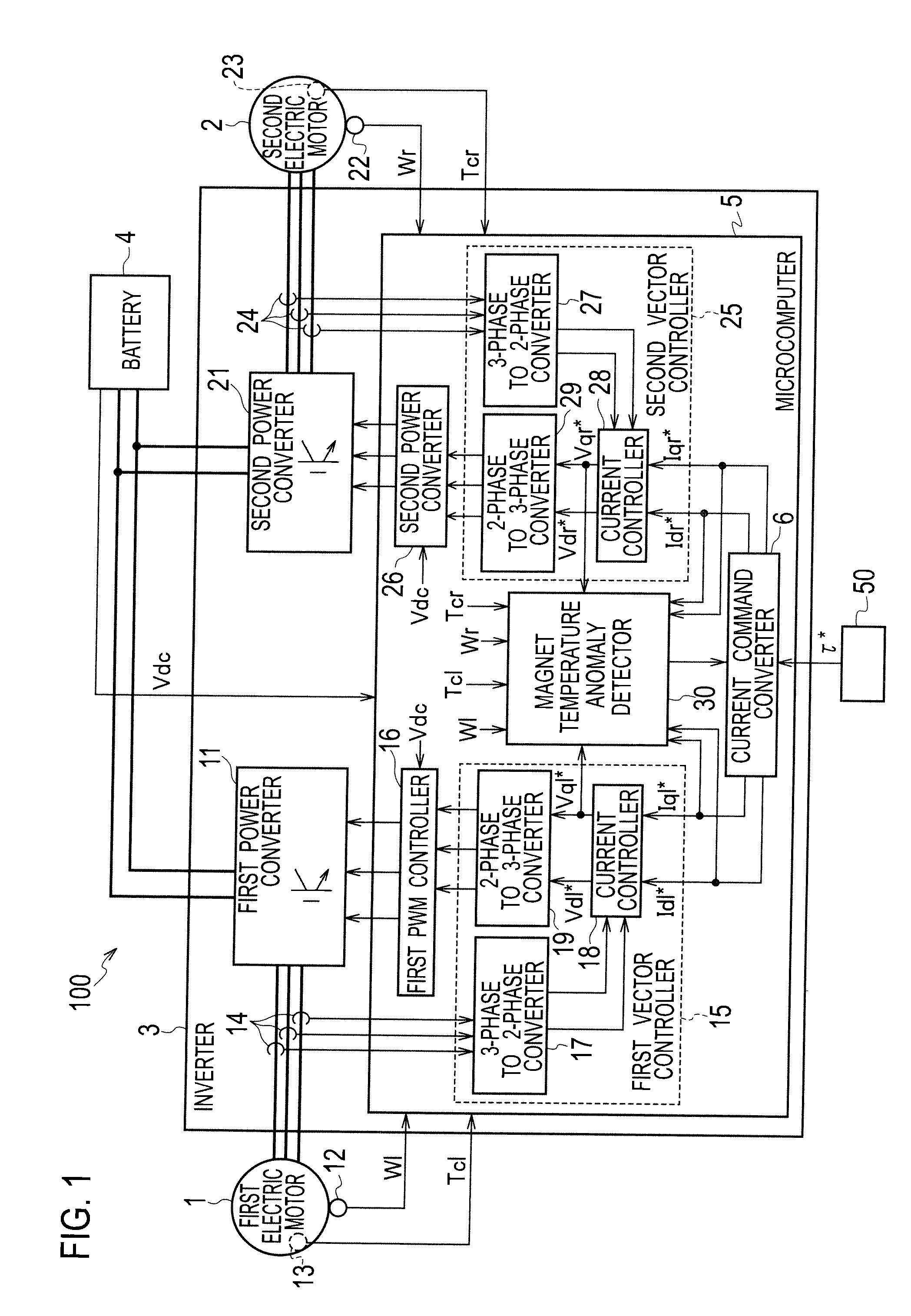
[0018]FIG. 1 is a schematic structure showing a driving control system 100 of an electric vehicle to which the present invention is applied. The driving control system 100 includes two permanent magnet synchronous electric motors 1, 2 for independently driving left and right wheels of the electric vehicle, an inverter 3 for driveably controlling the two permanent magnet synchronous electric motors 1, 2, and a battery 4 serving as an electric power supply.
[0019]A direct current power from the battery 4 is converted into an alternating current power by a first power converter 11 of the inverter 3 and then the alternating current power is supplied to the first electric motor 1 (of the two permanent magnet synchronous electric motors 1, 2) which rotates the left driving wheel of the electric vehicle. When ON / OFF operations of a switching element such as IGBT are PWM-controlled, the first power converter 11 converts the direct current power from the battery 4 into a desired alternating c...
second embodiment
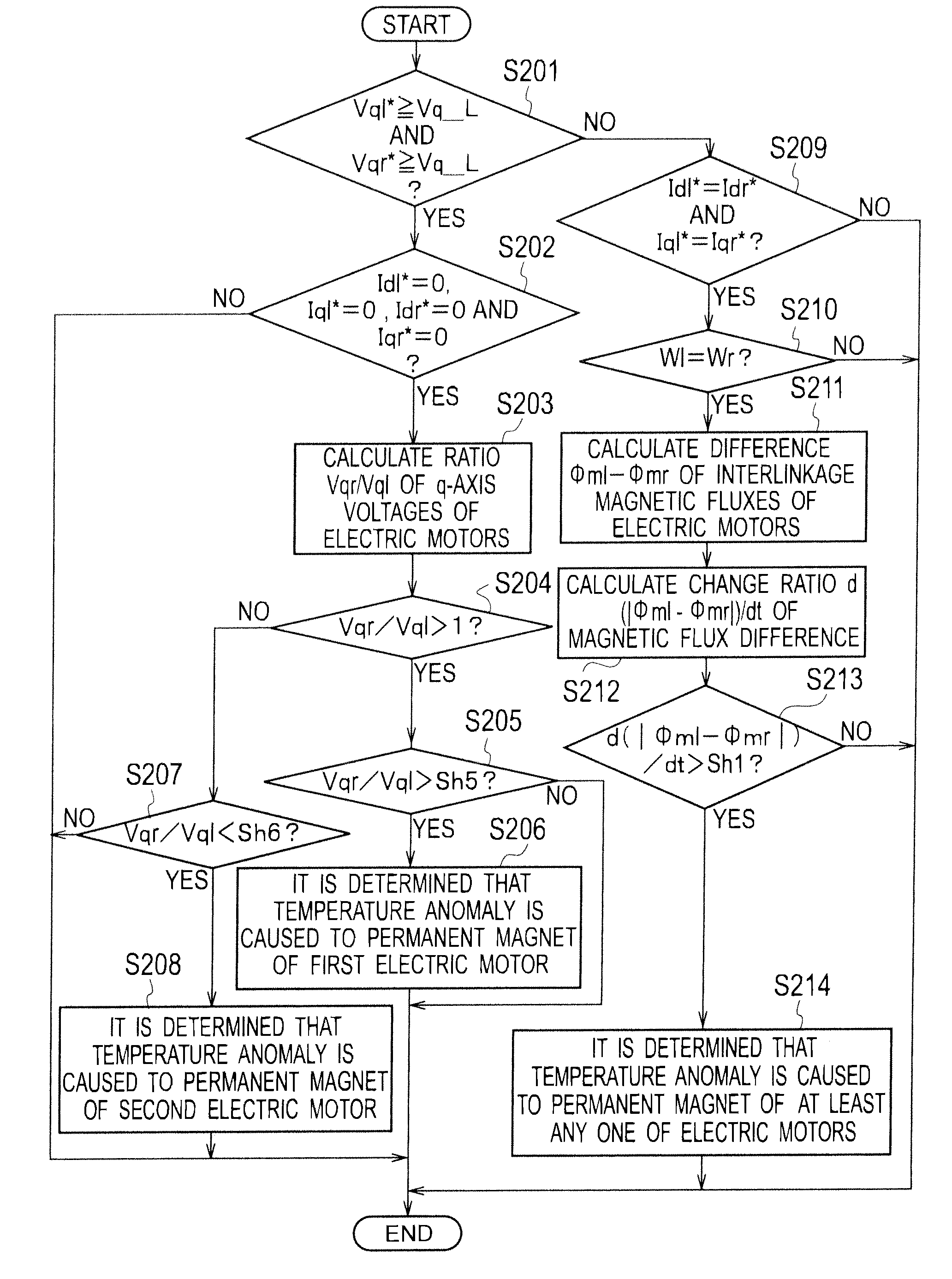
[0051]Next, the second embodiment of the present invention will be set forth. Like the first embodiment, the anomaly detector of the present invention as a function of the microcomputer 5 incorporated in the inverter 3 is realized according to the second embodiment, where the control structure is like that of the first embodiment, however, the processing at the magnet temperature anomaly detector 30 provided in the microcomputer 5 is slightly different from that of the first embodiment. That is, according to the first embodiment, the anomaly of the magnet temperature is detected by using the difference Vql−Vqr between the q-axis voltage Vql of the first electric motor 1 and the q-axis voltage Vqr of the second electric motor 2, however, according to the second embodiment, a ratio Vqr / Vql of the q-axis voltages is calculated in addition to the difference Vql−Vqr of the q-axis voltages of the electric motors 1, 2 and the temperature anomaly of the permanent magnets of the electric mot...
third embodiment
[0080]Next, the third embodiment of the present invention will be set forth. According to the third embodiment, on the premise that the temperature anomaly of the permanent magnets of the electric motors 1, 2 is detected by a method same as that according to the second embodiment, positively providing a timing at which the winding wire currents Id, Iq (Idl, Iql; Idr, Iqr) of the electric motors 1, 2 are each 0 increases a scene which makes it possible to implement the determination by using the ratio Vqr / Vql of the q-axis voltages. Hereinafter, only differences of the third embodiment from those of the second embodiment will be set forth.
[0081]As shown by the above expression (5) set forth according to the second embodiment, under the condition that the winding wire currents Id, Iq (Idl, Iql; Idr, Iqr) of the electric motors 1, 2 are each 0, the terms of the winding wire resistance R and the terms of the winding wire inductances Ld, Lq in the above expression (4) can be deleted, thu...
PUM
 Abstract
Description
Claims
Application Information
 - R&D
- Intellectual Property
- Life Sciences
- Materials
- Tech Scout
- Unparalleled Data Quality
- Higher Quality Content
- 60% Fewer Hallucinations
Browse by: Latest US Patents, China's latest patents, Technical Efficacy Thesaurus, Application Domain, Technology Topic, Popular Technical Reports.
© 2025 PatSnap. All rights reserved.Legal|Privacy policy|Modern Slavery Act Transparency Statement|Sitemap|About US| Contact US: help@patsnap.com


