Method And Apparatus For Reconstructing In-Cylinder Pressure And Correcting For Signal Decay

Active Publication Date: 2012-06-14
WESTPORT FUEL SYST CANADA INC
View PDF7 Cites 33 Cited by
  • Summary
  • Abstract
  • Description
  • Claims
  • Application Information

AI Technical Summary

Benefits of technology

[0024]In one embodiment, to operate the control system in a current mode, the control system further comprises a resistor electrically connected in parallel to the vibration sensor. With the disclosed system an advantage of operating in a current mode is that it does not require using charge am

Problems solved by technology

However, it can be impractical to employ such instrumentation in a mass produced engine, because in addition to being intrusive and/or being subjected to a harsh environment in the location where they are installed, such sensors can also be expensive and lack the durability needed for reliable and prolonged everyday use.
Engine knock correlates to violent combustion events that can be caused by pre-mature and uncontrolled detonation of the charge inside the combustion chamber, caused, for example, if an Otto-Cycle engine has been fuelled with a fuel that has an octane rating, which is too low, or if spark timing is too early, or if deposits in a combustion chamber create hot spots that cause early ignition.
In a Diesel-Cycle engine, engine knock can be caused, for example, if fuel injection timing is too early.
Engine knock can cause serious damage to the engine.
Because there is a relatively large difference between the reference signal and the signal when engine knock is detected the accuracy of the knock sensor is relatively unimportant.
Without processing the raw sign

Method used


Image

  • Method And Apparatus For Reconstructing In-Cylinder Pressure And Correcting For Signal Decay
  • Method And Apparatus For Reconstructing In-Cylinder Pressure And Correcting For Signal Decay
  • Method And Apparatus For Reconstructing In-Cylinder Pressure And Correcting For Signal Decay

Examples


Embodiment Construction

)

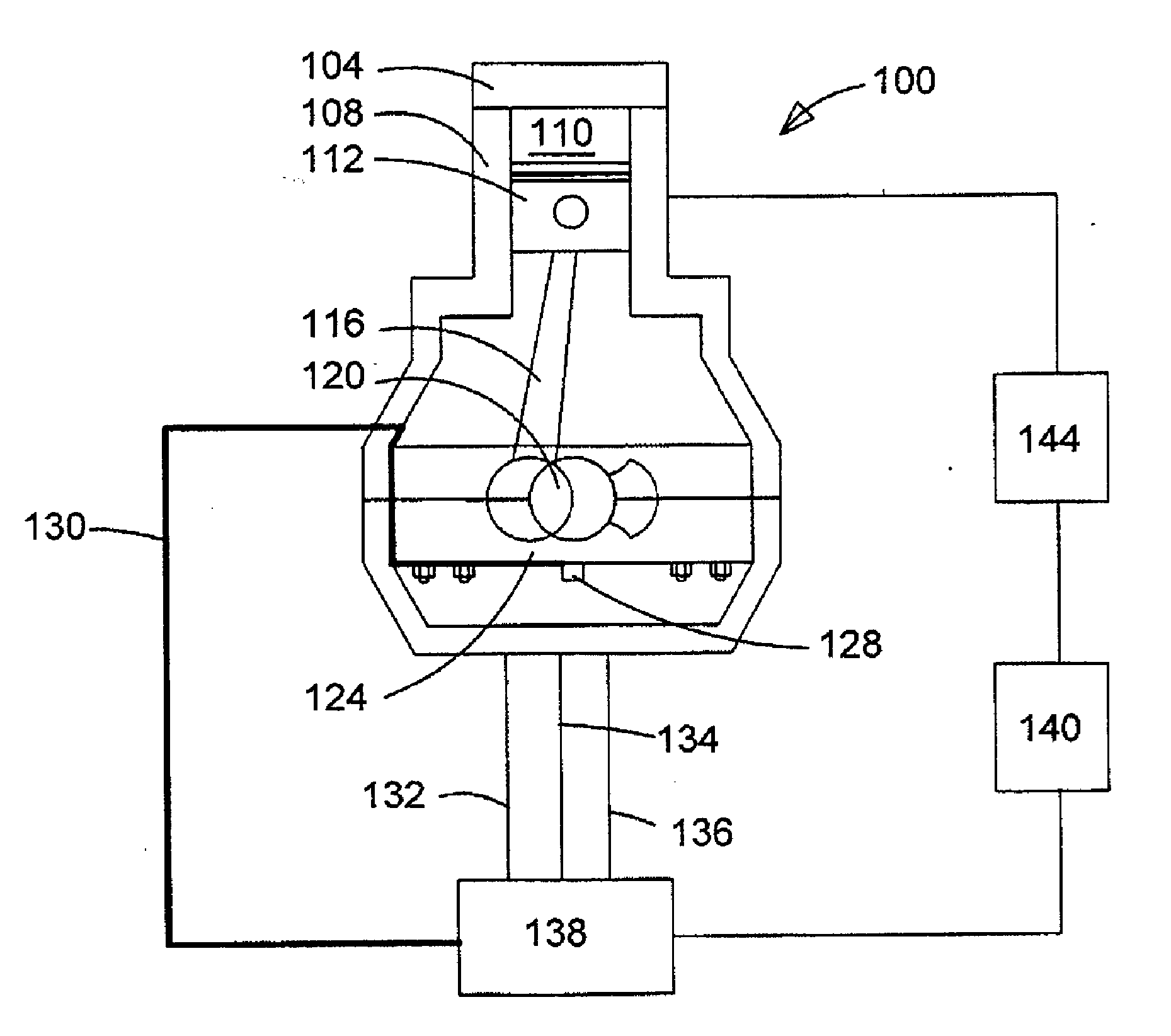
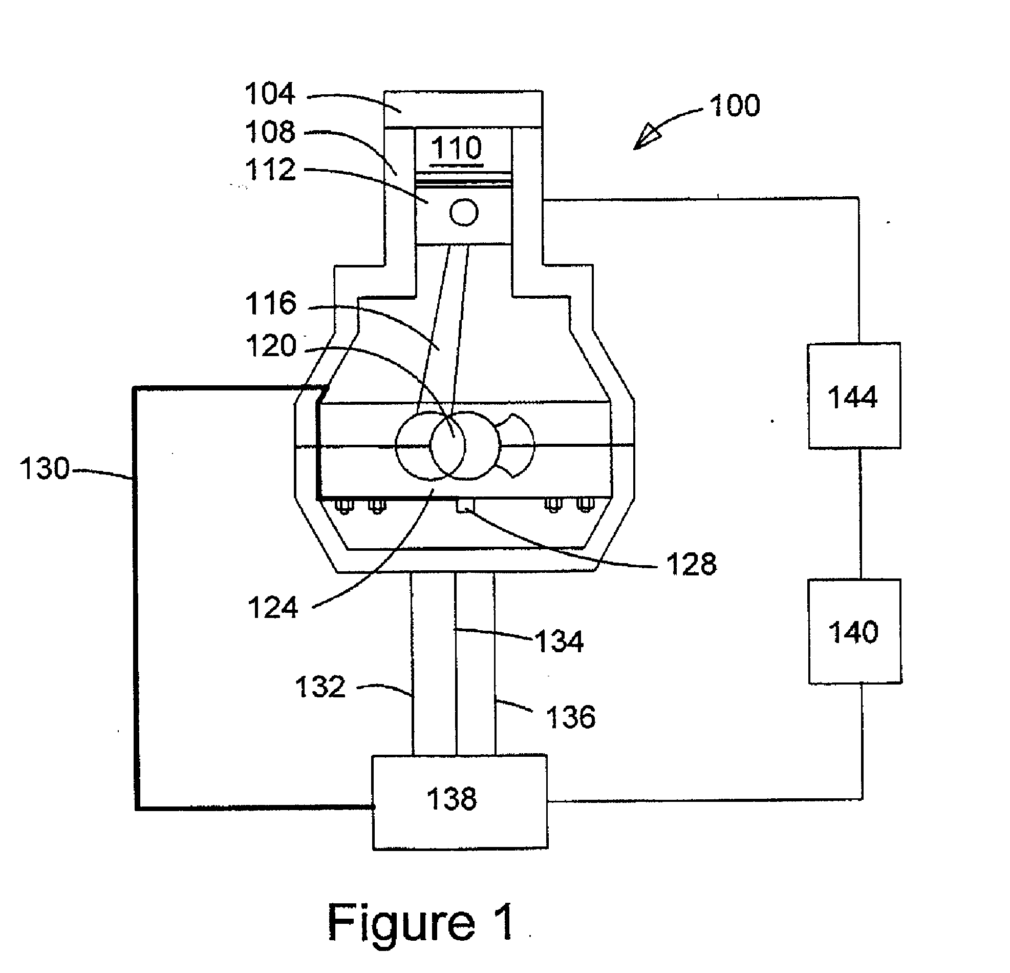
[0032]FIG. 1 schematically illustrates an internal combustion engine with a control system that can reconstruct the in-cylinder pressure for internal combustion engine 100 from a vibration signal collected by vibration sensor 128. The control system then uses the reconstructed pressure data to control combustion characteristics. Engine 100 includes combustion chamber 110, which in this example is defined by cylinder 108, cylinder head 104 and piston 112. For simplicity only the combustion chamber of one cylinder of an engine is shown although persons skilled in the technology will understand that the engine typically has two or more cylinders, and when there is a plurality of cylinders they can be arranged in banks. Piston 112 is reciprocable within cylinder 108, and the reciprocating motion of piston 112 is translated into rotation of crankshaft 120 via connecting rod 116 which is operatively attached at opposite ends to piston 112 and crankshaft 120 respectively. Intake and exhau...


PUM


Abstract

A method comprises steps for reconstructing in-cylinder pressure data from a vibration signal collected from a vibration sensor mounted on an engine component where it can generate a signal with a high signal-to-noise ratio, and correcting the vibration signal for errors introduced by vibration signal charge decay and sensor sensitivity. The correction factors are determined as a function of estimated motoring pressure and the measured vibration signal itself with each of these being associated with the same engine cycle. Accordingly, the method corrects for charge decay and changes in sensor sensitivity responsive to different engine conditions to allow greater accuracy in the reconstructed in-cylinder pressure data. An apparatus is also disclosed for practicing the disclosed method, comprising a vibration sensor, a data acquisition unit for receiving the vibration signal, a computer processing unit for processing the acquired signal and a controller for controlling the engine operation based on the reconstructed in-cylinder pressure.

Description

CROSS-REFERENCE TO RELATED APPLICATION(S)[0001]This application is a continuation of International Application No. PCT / CA2010 / 001143, having an international filing date of Jul. 27, 2010, entitled “Method And Apparatus For Reconstructing In-Cylinder Pressure And Correcting For Signal Decay”. The '143 international application claimed priority benefits, in turn, from Canadian Patent Application No. 2,673,216 filed Jul. 31, 2009. The '143 international application is hereby incorporated by reference herein in its entirety.STATEMENT REGARDING FEDERALLY SPONSORED RESEARCH[0002]This invention was made with Government support under Contract No. DE-FC26-06NT42967 awarded by the United States Department of Energy. The Government has certain rights in the invention.FIELD OF THE INVENTION[0003]The present invention relates to a method and apparatus for internal combustion engines that involves reconstructing in-cylinder pressure from a vibration signal and correcting for signal decay to impro...

Claims


Application Information

Patent Timeline
IPC IPC(8): G06G7/70G01M15/12G06F19/00
CPCF02D35/024G01M15/08G01M15/12F02D41/28F02D2041/288F02D2041/1432F02D2041/281F02D2041/286F02D35/027
Inventor HUANG, JIAN
Owner WESTPORT FUEL SYST CANADA INC
Why Eureka
Try Eureka