Induction Welded Waterproofing

a technology of induction welding and waterproofing, which is applied in the field of subgrade waterproofing, can solve the problems of increasing installation cost, reducing installation efficiency, and requiring additional steps or equipment, so as to reduce installation efficiency, increase installation cost, and increase the time required for operating equipmen

Inactive Publication Date: 2012-06-21
AMCOL INTERNATIONAL CORPORATION
View PDF29 Cites 6 Cited by
  • Summary
  • Abstract
  • Description
  • Claims
  • Application Information

AI Technical Summary

Benefits of technology

[0004]Attaching membrane waterproofing to shoring in a manner that does not penetrate the waterproofing membrane has several traditional solutions that favor small membrane sheet or panel sizes. Large prefabricated or factory fabricated panels pose challenges that require additional steps and or equipment. These additional steps reduce installation efficiency and combined with the additional equipment increase installation cost. Placing large prefabricated panels on large shoring walls requires access behind the waterproofing membrane panels. Typically, this requires lifting a panel that is affixed at the top, from the bottom and allowing it to drape down to available fastening tabs. This step greatly increases the time required for operating the equipment used to suspend the membrane panels; typically a crane or lift of some type. Alternately, another method requires access to the back side of the membrane to weld the thermoplastic membrane to thermoplastic fastening discs. Bored rock tunnels additionally challenge typical membrane installation methods due to the confined space and inverted arch configuration of the structure. Unique to all other waterproofing applications, a bored rock tunnel is the only type of waterproofing that requires fixing the waterproofing membrane to overhead shoring; and specifically to a shoring surface with a closing radius.

Problems solved by technology

Large prefabricated or factory fabricated panels pose challenges that require additional steps and or equipment.
These additional steps reduce installation efficiency and combined with the additional equipment increase installation cost.
This step greatly increases the time required for operating the equipment used to suspend the membrane panels; typically a crane or lift of some type.
Bored rock tunnels additionally challenge typical membrane installation methods due to the confined space and inverted arch configuration of the structure.

Method used


Image

  • Induction Welded Waterproofing
  • Induction Welded Waterproofing
  • Induction Welded Waterproofing

Examples


example 1

The Following Reference Numbers Correspond to FIGS. 8A to 8F

[0083]As used herein, the term “salt water” refers to aqueous solutions that contain acids, bases, and / or, preferably salts. Preferably, the salt water contains ions that for example can be H+, Na+, K+, Mg2+, Ca2+, and / or Al3+. One method for determining if a aqueous solution is salt water is through a conductivity measurement. Conductivity is a measure of the level of ion concentration of a solution. The more salts, acids or bases are dissociated, the greater the conductivity of the solution. In water or wastewater it is mainly a matter of the ions of dissolved salts, and consequently the conductivity is an index of the salt load in wastewater. The measurement of conductivity is generally expressed in S / cm (or mS / cm) which is the product of the conductance of the test solution and the geometric factor of the measuring cell. For purposes of this invention, salt water is defined as water with a conductivity greater than 15 m...

example 2

The Following Reference Numbers Correspond to FIG. 9-12

[0131]Conductivity is a measure of the level of ion concentration of a solution. The more salts, acids or bases are dissociated, the greater the conductivity of the solution. In water or wastewater it is mainly a matter of the ions of dissolved salts, and consequently the conductivity is an index of the salt load in wastewater. The measurement of conductivity is generally expressed in S / cm (or mS / cm) which is the product of the conductance of the test solution and the geometric factor of the measuring cell. For purposes of this invention, high conductivity waters are defined as waters with conductivity greater than 1 mS / cm. Conductivity can be measured using a variety of commercially available test instruments such as the Waterproof PC 300 hand-held meter made by Eutech Instruments / Oakton Instruments.

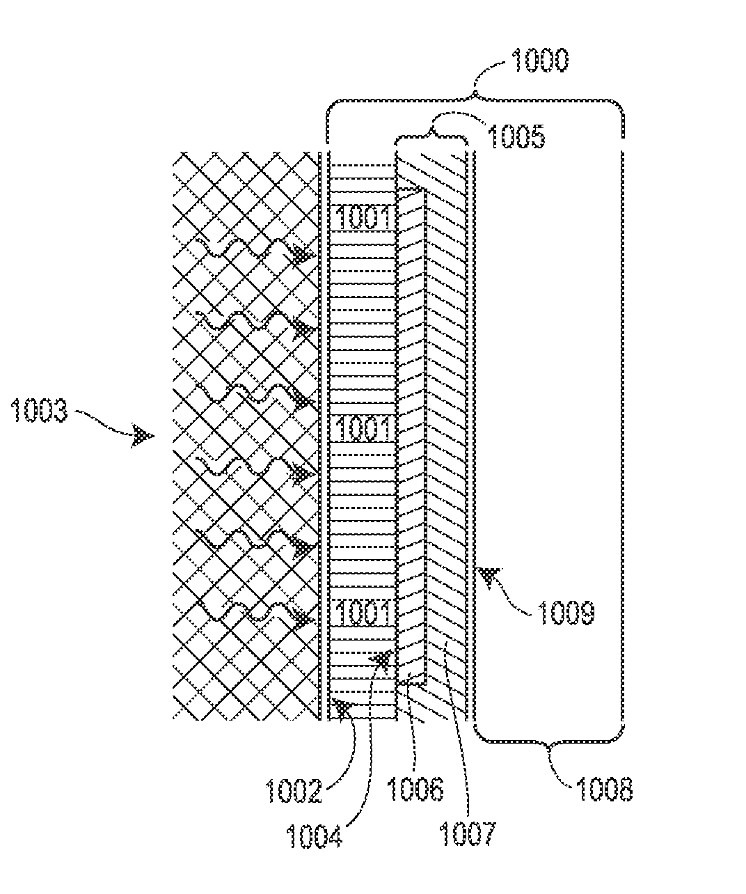
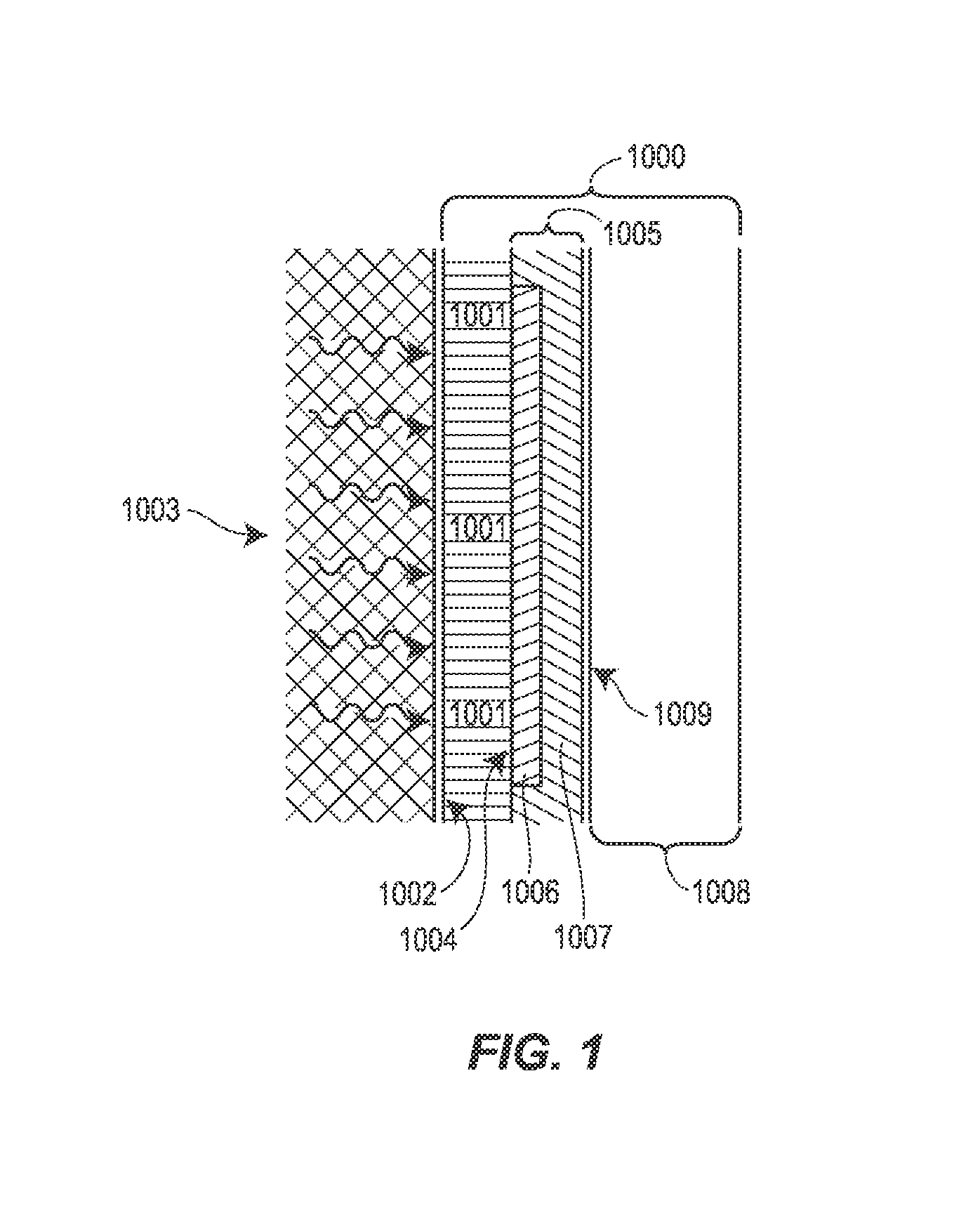
[0132]In the preferred embodiment, the partially cross-linked acrylamide / acrylate / acrylic acid copolymer is incorporated as a laye...


PUM

PropertyMeasurementUnit
wt. %aaaaaaaaaa
lengthaaaaaaaaaa
lengthaaaaaaaaaa

Abstract

In accordance with an embodiment of the disclosure, A water-proofing laminate includes a drainboard having a first surface positioned against a hydraulic source and a second surface opposed to the first surface, a fastener plate positioned against the second surface of the drainboard securing the drainboard to the hydraulic surface, the fastener plate comprising a conductive element and a thermoplastic resin, and a self-healing hydraulic barrier comprising a thermoplastic surface adjoined to a geotextile and carrying a water-absorbent material, the thermoplastic surface inductively welded to the fastener plate.

Description

CROSS-REFERENCE TO RELATED APPLICATION[0001]The benefit under 35 U.S.C. §119(e) of U.S. Provisional Patent Application Ser. No. 61 / 411,002 filed Nov. 8, 2010, is hereby claimed, and its entire disclosure is incorporated herein by reference.FIELD OF DISCLOSURE[0002]The present disclosure is applicable to sub-grade waterproofing, preferably the formation of a self-healing waterproof barrier prior to the pouring or placement of the structural element to be waterproofed.BRIEF DESCRIPTION OF RELATED TECHNOLOGY[0003]Traditionally, the membrane is welded to thermoplastic fixing anchors placed over the cushion / drainage layer(s); then the thermoplastic membrane waterproofing sheets are welded to the fixing anchors with hand held air welding equipment. This requires the installer to get behind the suspended membrane from the top, bottom or sides of the suspended sheets in order to access the fixing anchors to weld them to the thermoplastic waterproofing membrane. There are other non-penetrati...

Claims


Application Information

Patent Timeline
Patent Type & Authority Applications(United States)
IPC IPC(8): B32B38/18B32B3/06E04F13/07
CPCB32B37/00B32B2038/166B32B2307/718B32B2307/7246B32B2309/02B32B2310/0812Y10T156/10E02D31/02E21D11/383B29D99/001B32B3/06Y10T428/24008B32B2419/00
Inventor CISNEROS, ROBERT
Owner AMCOL INTERNATIONAL CORPORATION
Why Eureka
Try Eureka