Nano-engineered ultra-conductive nanocomposite copper wire

a technology of nanocomposite copper wire and nano-engineered materials, which is applied in the direction of material nanotechnology, chemistry apparatus and processes, grain treatment, etc., can solve the problems of high efficiency, size and power consumption of all conventional electric machines and devices, and the inability to harness this potential. the effect of reducing the size of the wire, and reducing the cost of the wir

Inactive Publication Date: 2012-06-21
CLEVELAND STATE UNIVERSITY
View PDF2 Cites 23 Cited by
  • Summary
  • Abstract
  • Description
  • Claims
  • Application Information

AI Technical Summary

Benefits of technology

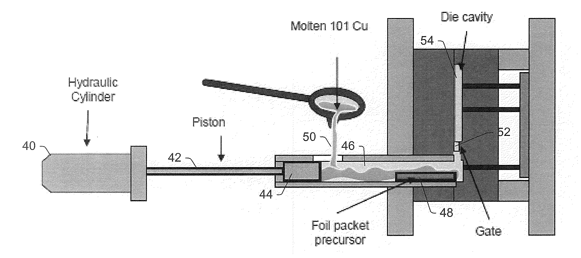
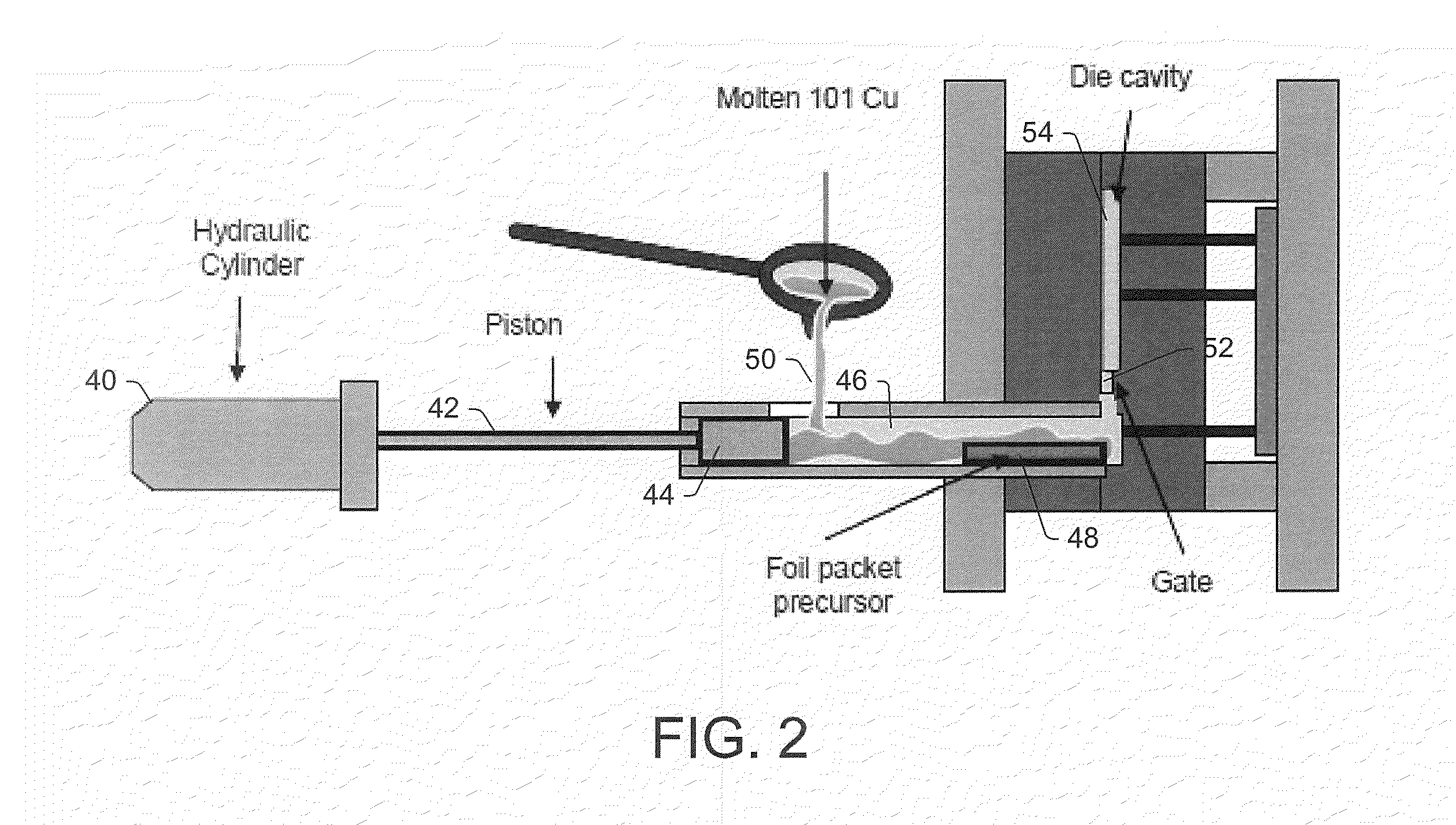
[0008]According to another aspect, a method of forming nano-composite copper wire comprises loading a piston chamber with a carbon nanotube (CNT) precursor, injecting the CNT precursor into a molten metal stream that is under pressure and traveling at high velocity into a die cavity to form a nano-composite mixture, and forcing the nano-composite mixture through a nozzle and into the die cavity, which has an internal diameter equal to or less than a diameter of the nozzle exit. The method further comp

Problems solved by technology

This defined the upper limits of the efficiency and consequently the size and power consumption of all conventional electric machines and devices.
Unfortunately, harnessing this potential has not been successful thus far because the nanotubes produced to-date are on the order of few millimeters in length and no one h

Method used


Image

  • Nano-engineered ultra-conductive nanocomposite copper wire
  • Nano-engineered ultra-conductive nanocomposite copper wire
  • Nano-engineered ultra-conductive nanocomposite copper wire

Examples


Embodiment Construction

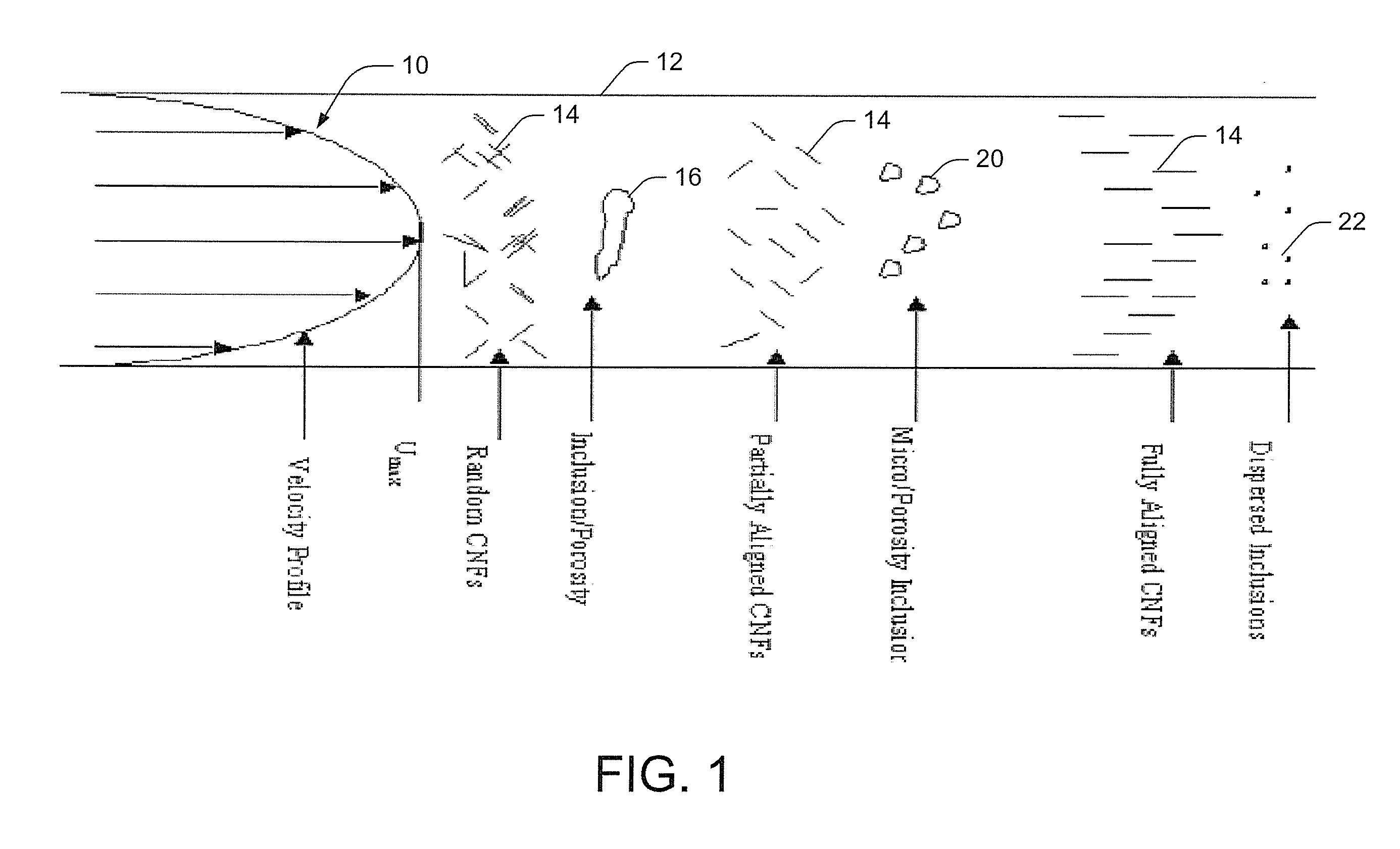
[0047]Referring now to the drawings wherein the showings are for purposes of illustrating the exemplary embodiments only and not for purposes of limiting the claimed subject matter. FIG. 1 illustrates a technique for generating nano-composite copper wire. In order to overcome the above-described obstacles, two main issues need to be addressed, which are: first, identifying and / or developing a manufacturing process that is capable of infusing, dispersing, and aligning carbon nanotubes in copper while minimizing the residual porosity in the matrix in order to form intimate electrical contacts; and second, identifying a type of nanotube that acts as a ballistic conductor and identifying a coating material such that the combination is suited for infusing into copper and has the potential for functioning in unison with copper to form a semi-bulk ballistic conductor, and thus produce the desired ultra-conductivity.

[0048]With these properties in mind, whether the copper is powder or molten...


PUM

PropertyMeasurementUnit
Temperatureaaaaaaaaaa
Lengthaaaaaaaaaa
Lengthaaaaaaaaaa

Abstract

Nano-composite structures are formed by pre-loading carbon nanotubes (CNTs) into at least one of a plurality of channels running the length of a cartridge, placing the pre-loaded cartridge in a piston chamber of a die-casting machine, creating a vacuum therein, and filing the piston chamber with molten metal to soak the pre-loaded cartridge and fill empty cartridge channels. Pressure is applied via the piston to eject the carbon nanotubes and molten metal from the cartridge channels and inject the nano-composite mixture into a rod-shaped die cavity. The internal diameter of the cavity is equal to or less than the final diameter of the nozzle. The nano-composite mixture is cooled to form a solid nano-composite rod having the first predetermined diameter, wherein the carbon nanotubes are aligned in a non-random manner. Furthermore, drawing down the nano-composite rod to smaller diameter wire further disperses the nanotubes along the length of the wire.

Description

CROSS-REFERENCE TO RELATED APPLICATIONS[0001]This application claims priority to U.S. Provisional Application Ser. No. 61 / 424,218, entitled NANO-ENGINEERED ULTRA-CONDUCTIVE NANOCOMPOSITE COPPER WIRE and filed on Dec. 17, 2010, the entirety of which is incorporated by reference herein.[0002]The U.S. Government has a paid-up license in this invention and the right in limited circumstances to require the patent owner to license others on reasonable terms as provided for by the terms of Subcontract GTS-S-11-078 awarded by CERDEC-Army Power Div.BACKGROUND OF THE INVENTION[0003]This invention relates to a method and apparatus for manufacturing ultra-conductive and / or ultra-strong nano-composite wire. While the invention is particularly directed to the art of wire manufacture, and will be thus described with specific reference thereto, it will be appreciated that the invention will have usefulness in other fields and applications including the manufacturing of ultra-conductive and / or ultra...

Claims


Application Information

Patent Timeline
IPC IPC(8): B22D19/00B22D25/02B02C17/16B22D27/15B82Y30/00B82Y40/00
CPCB22D17/14B22D27/15B22F5/12B22F2998/00B22F2998/10B82Y30/00B02C7/16C22C2026/002B22F3/17B21C37/047B22D17/04B22D19/02C22C47/12B21C37/045B21C1/003C01B2202/10C22C1/101C22C1/1015C22C1/1036C01B32/16C01B32/172C22C1/1073
Inventor NAYFEH, TAYSIR H.WIEDERHOLT, ANITA M.
Owner CLEVELAND STATE UNIVERSITY
Why Eureka
Try Eureka