Wireless Network System and Wireless Communication Device

a wireless communication and network system technology, applied in the field of wireless network systems, can solve the problems of high cost, high difficulty in installation, maintenance and management of cables, and low disturbance tolerance of wireless communication in cable communication, and achieve the effect of improving reliability and stability of communication, and without any deterioration of communication performan

Inactive Publication Date: 2012-06-21
HITACHI LTD
View PDF4 Cites 32 Cited by
  • Summary
  • Abstract
  • Description
  • Claims
  • Application Information

AI Technical Summary

Benefits of technology

[0021]According to the aspect of the present invention, the reliability and stability of a communication can be improved with a low electric power without any deterioration of a communication performance.

Problems solved by technology

However, under the existing circumstances, in facilities of an industrial infrastructure field such as large-scaled manufacturing line factories or plants, a total laying length of network communication cables to be used becomes a few km, and the installation, maintenance, and management of the cables have been high in the degree of difficulty and the costs.
However, the wireless communication is low in disturbance tolerance in a cable communication and in the stability from the viewpoint of a communication environment change.
Accordingly, the probability of failure in the wireless communication becomes high as compared with the cable communication.
Also, in the wireless communication, because multiple communication devices share the same space, electric waves may influence each other and interfere with each other to deteriorate the communication performance.
That is, the communication performances represented by a bit error rate (transmission error rate per one bit of data), a latency (delay time necessary for data transmission), and a throughput (rate for data transmission) in the wireless communication network may be deteriorated with a temporal or spatial change of the electric wave environment, and data transmission in the wireless communication become unstable (that is, reliability of data transmission is reduced).
In the industrial infrastructure field, particularly, because the high stability and reliability of the data transmission are required, the securement of reliability becomes a barrier to wireless communication network introduction.

Method used


Image

  • Wireless Network System and Wireless Communication Device
  • Wireless Network System and Wireless Communication Device
  • Wireless Network System and Wireless Communication Device

Examples


first embodiment

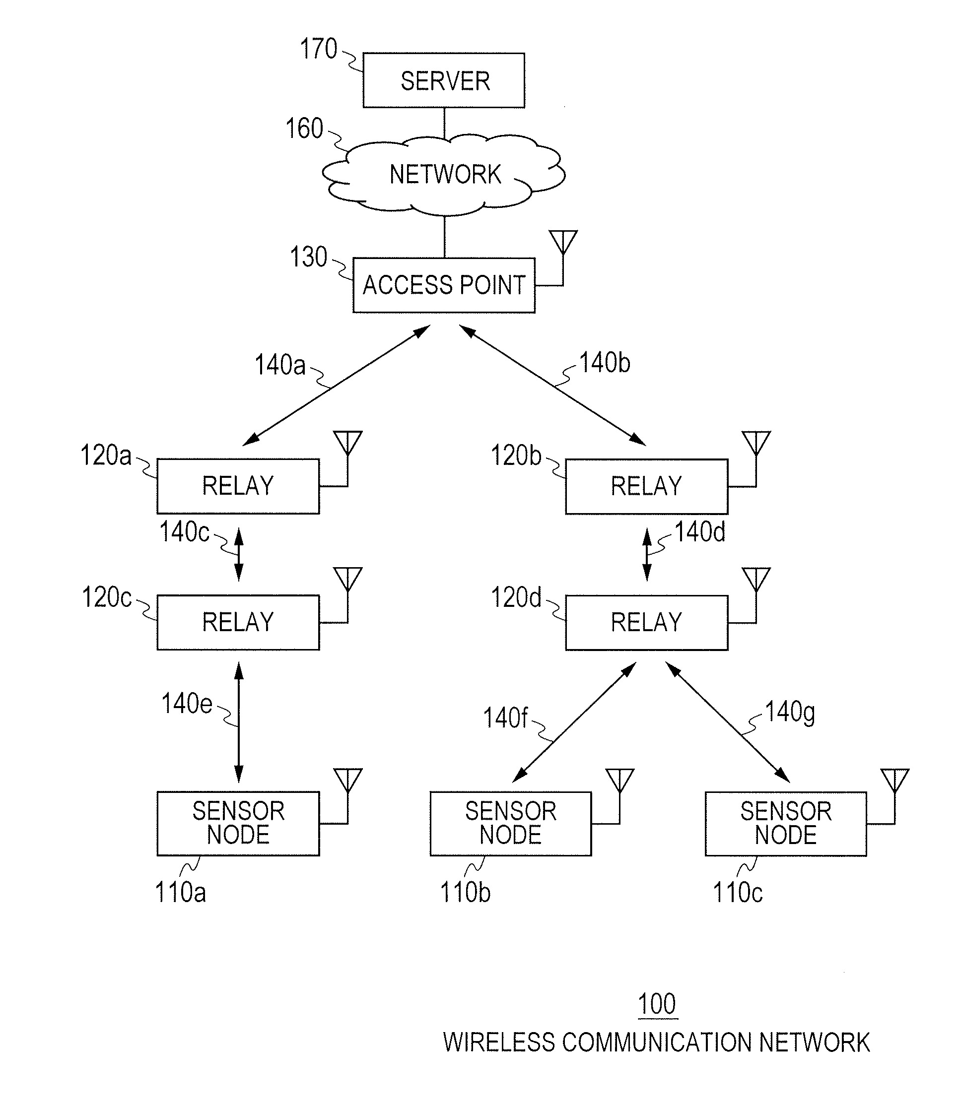
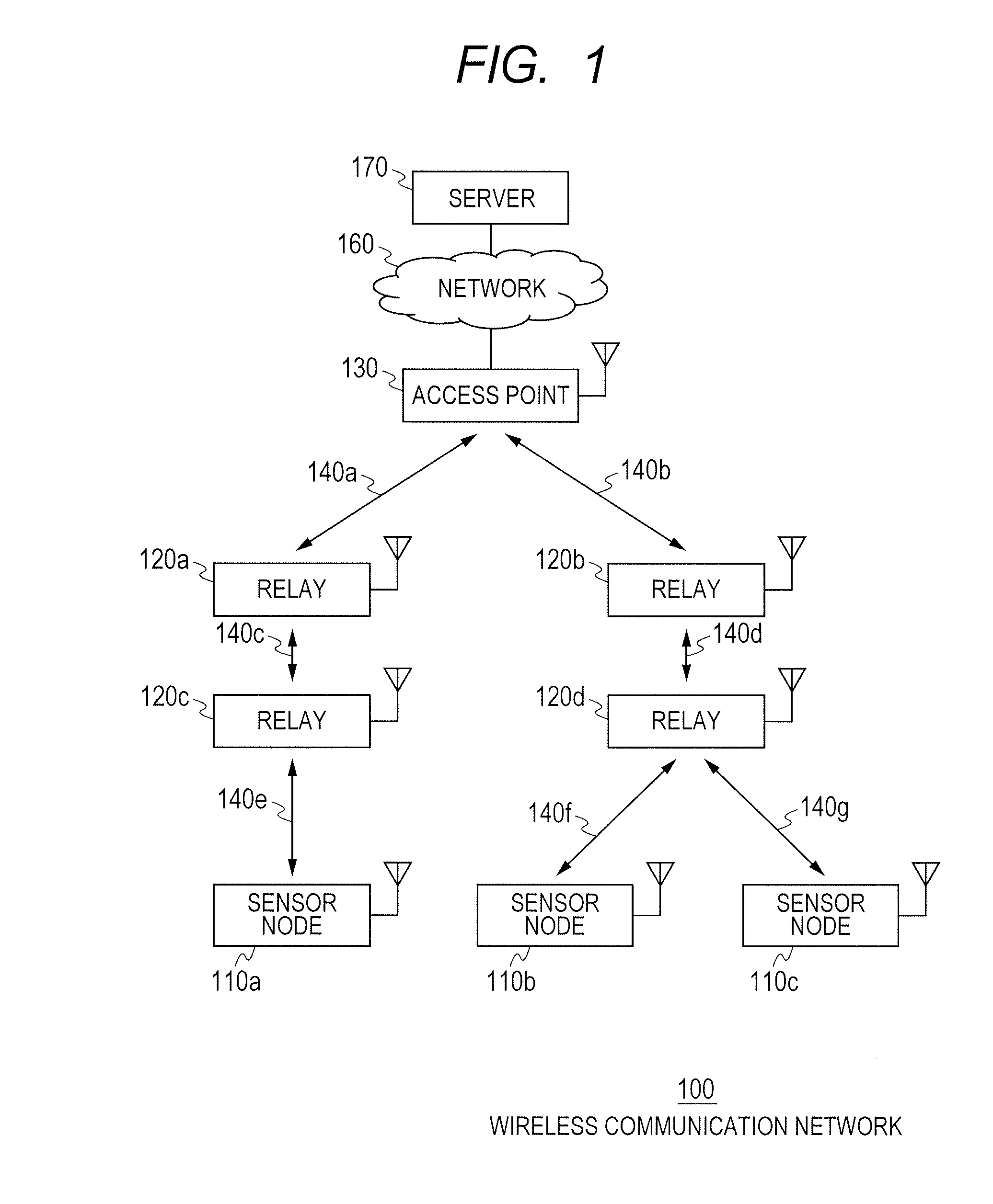
[0032]FIG. 1 is a block diagram illustrating a configuration of a wireless communication network 100 according to a first embodiment of the present invention

[0033]The wireless communication network 100 includes a sensor node 110 (110a, 110b, and 110c), a relay 120 (120a, 120b, 120c, and 120d), an access point 130, a network 160, and a server 170. In the following description, the sensor node 110, the relay 120, and the access point 130 will be called “wireless communication device”.

[0034]Each of the sensor node 110, the relay 120, and the access point 130 is a computer including a processor, a memory, an auxiliary storage device, and a network interface. The processor provided in each of the sensor node 110, the relay 120, and the access point 130 implements the respective functions by executing programs retained in a memory provided in each processor.

[0035]Further, the sensor node 110 or the relay 120 is equipped with a sensor device for measuring a physical amount such as a temper...

second embodiment

[0165]FIG. 8 is a sequence diagram illustrating a basic communication in a multihop wireless network according to a second embodiment of the present invention.

[0166]A sequence illustrated in FIG. 8 represents a wireless communication in the wireless communication network 100 in which one sensor node 110, one relay 120, and one access point 130 are provided.

[0167]The access point 130 transmits a time synchronization command to the relay 120 (211), and receives an acknowledge signal from the relay 120 (212). The relay 120 transmits the time synchronization command to the sensor node 110 (213), and receives the acknowledge signal from the sensor node 110 (214). Each wireless communication device receives the acknowledge signal to determine whether the wireless communication device to which the packet 150 is transmitted has normally received the packet 150, or not.

[0168]Subsequently, the sensor node 110 transmits the sensor measurement data to the relay 120 (215), and receives the ackno...


PUM


Abstract

A wireless communication device includes a sensor processing unit that generates sensor data including a measurement result acquired by a sensor; a communication measurement unit that generates communication quality data including a communication state for transmitting a packet; a compression determination unit that determines compression rates of first sensor data and first communication quality data according to the contents of the first sensor data including the transmitted sensor data and the generated sensor data or the contents of the first communication quality data including the transmitted sensor data and the generated communication quality data; a compression unit that compresses the first sensor data and the first communication quality data according to the determined compression rates; and a wireless communication unit that transmits a packet including the compressed first sensor data and the compressed first communication quality data to another wireless communication device or the access point.

Description

CLAIM OF PRIORITY[0001]The present application claims priority from Japanese patent application JP 2010-279604 filed on Dec. 15, 2010, the content of which is hereby incorporated by reference into this application.FIELD OF THE INVENTION[0002]The present invention relates to a wireless network system, and more particularly to a wireless network system that transmits sensor data using a multihop technology.BACKGROUND OF THE INVENTION[0003]In recent years, with a remarkable improvement of a computer performance, a communication performance required for a network communication that connects among multiple computers has been also remarkably improved. In the network communication, computers are connected with each other by the aid of cables, and a request for improvement of the performance has been met by increasing the number of cables. However, under the existing circumstances, in facilities of an industrial infrastructure field such as large-scaled manufacturing line factories or plant...

Claims


Application Information

Patent Timeline
Patent Type & Authority Applications(United States)
IPC IPC(8): H04W24/00H04W4/38
CPCH04L12/2602H04L43/00H04L67/12H04W4/006H04W24/10Y02B60/50H04W84/18H04L69/04H04L1/0002H04L1/0014H04L2001/0097H04W28/06H04W4/38Y02D30/70
Inventor MIYAZAKI, MASAYUKIMIZUGAKI, KENICHIKOKUBO, MASARUNAGAISHI, HIDEYUKIKOBAYASHI, NOBUHISA
Owner HITACHI LTD
Why Eureka
Try Eureka