Optical packet switching system

a packet switching and optical packet technology, applied in data switching networks, multiplex communication, digital transmission, etc., can solve the problems of large fluctuation in the gain of an edfa, inability of edfa to control the gain of each optical packet, and waste of bandwidth accordingly

Inactive Publication Date: 2012-06-21
FUJITSU LTD
View PDF9 Cites 12 Cited by
  • Summary
  • Abstract
  • Description
  • Claims
  • Application Information

AI Technical Summary

Benefits of technology

[0014]The noise superimposition device may control the amount of cross talk based on bit error rate information detected by the light receiver device for receiving an optical packet signal from the optical amplifier device.
[0015]The noise superimposition device may control the amount of cross talk so that the bit error rate detected by the optical receiver device is equal to or lower than a predetermined threshold value.
[0018]The noise superimposition device may control the amount of ASE noise so that the bit error rate detected by the optical receiver device is equal to or lower than a predetermined threshold value.

Problems solved by technology

When the transmission is based on IP packets, no significant information is transmitted absent any data so that the bandwidth is wasted accordingly.
Therefore, an EDFA cannot control the gain of each optical packet, which lasts on the order of nsec or μsec.
Therefore, large variation in the average optical power caused by variation in packet density or an optical switch characterized by high extinction ratio is a factor that may result in large fluctuation in the gain of an EDFA.
This might adversely affect the bit error rate characteristics of the optical receiver for receiving the optical packet signal.

Method used


Image

  • Optical packet switching system
  • Optical packet switching system
  • Optical packet switching system

Examples


first embodiment

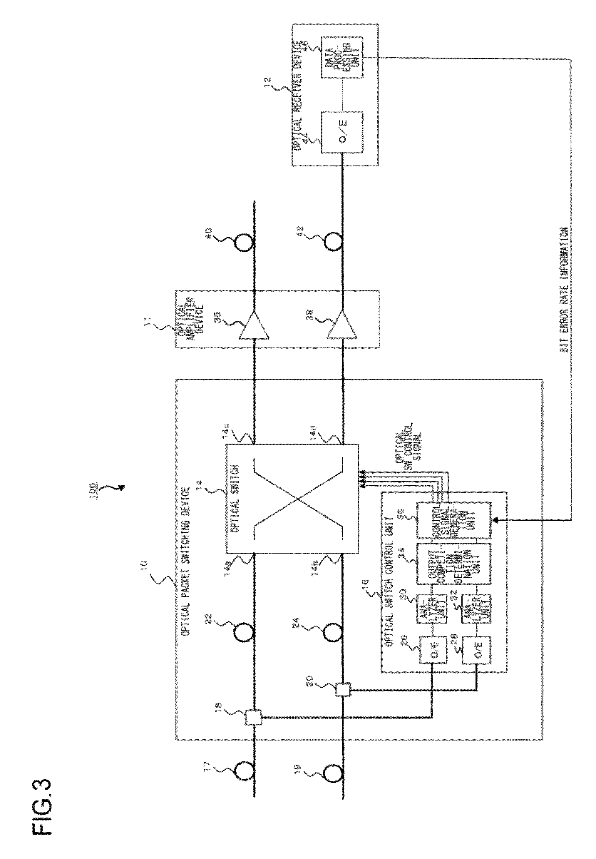
[0035]FIG. 3 shows an optical packet exchange system according to the first embodiment of the present invention. As shown in FIG. 3, an optical packet exchange system 100 comprises a 2-input×2-output optical packet switching device 10, an optical amplifier device 11, and an optical receiver device 12.

[0036]The optical packet switching device 10 is provided with the function of switching the path of, i.e., routing, an input optical packet signal and outputting the signal accordingly. As shown in FIG. 3, the optical packet switching device 10 comprises an optical switch 14, an optical switch control unit 16, a first optical coupler 18, a second optical coupler 20, a first optical delay line 22, and a second optical delay line 24.

[0037]The optical packet signal input to the optical packet switching device 10 via a optical transmission path 17 is input to the first optical coupler 18. The first optical coupler 18 causes the optical packet signal to branch into two signals. One of the op...

second embodiment

[0058]FIG. 5 shows an optical packet switching system according to the second embodiment of the present invention. Those components of the optical packet switching system 100 shown in FIG. 5 that are identical or corresponding to the components of the optical packet switching system shown in FIG. 3 are denoted by like symbols and a detailed description is omitted.

[0059]As shown in FIG. 5, the optical packet switching system 100 according to this embodiment differs from the optical packet switching system 100 shown in FIG. 3 in that an ASE light source 48 is provided. The ASE light source 48 is provided in the optical packet switching device 10 and superimposes amplified spontaneous emission (ASE) noise on optical packet signals output from the first output port 14c and the second output port 14d of the optical switch 14 via a third optical coupler 50 and a fourth optical coupler 52.

[0060]Thus, according to the embodiment, the extinction ratio of an optical packet signal prior to inp...

third embodiment

[0063]FIG. 6 shows an optical packet switching system according to the third embodiment of the present invention. Those components of the optical packet switching system 100 shown in FIG. 6 that are identical or corresponding to the components of the optical packet switching system shown in FIG. 3 are denoted by like symbols and a detailed description is omitted.

[0064]As shown in FIG. 6, the optical packet switching system 100 shown in FIG. 6 differs from the optical packet switching system shown in FIG. 3 in that a dummy packet insertion unit 54 is provided. In this embodiment, the dummy packet insertion unit 54 is provided in the optical switch 14. The dummy packet insertion unit 54 has the function of inserting a dummy packet in an optical signal in accordance with a control signal from the control signal generation unit 35.

[0065]FIGS. 7A-7C illustrate the operation of the optical packet switching system according to the third embodiment. FIG. 7A shows an optical packet signal in...


PUM


Abstract

An optical packet switching system includes: an optical packet switching device configured to route and output an input optical packet signal; an optical amplifier device provided in a stage subsequent to the optical packet switching device; and a dummy packet insertion device configured to insert a dummy packet in an optical packet signal prior to input to the optical amplifier device. A dummy packet includes a flag indicating that the packet is a dummy packet.

Description

BACKGROUND OF THE INVENTION[0001]1. Field of the Invention[0002]The present invention relates to an optical packet switching system in which packet-by-packet optical packet switching is enabled by driving an optical switch according to routing information assigned to an optical packet signal.[0003]2. Description of the Related Art[0004]The technology of switching the path depending on the wavelength in an optical transmission system based on wavelength division multiplexing (WDM) and by employing a wavelength selective switch (WSS) is in practical use. One of the next-generation technologies studied is an optical packet switching system in which the path is switched in smaller units, namely, IP packets (10 Gigabit Ethernet (registered trademark) signals, etc.). Each packet is converted in format into an optical packet and routed by using an ultrahigh-speed optical switch (see e.g., patent document No. 1).[0005]When the transmission is based on IP packets, no significant information ...

Claims


Application Information

Patent Timeline
Patent Type & Authority Applications(United States)
IPC IPC(8): H04J14/00H04B10/27H04B10/11H04L12/701
CPCH04J14/0212H04J14/0275H04Q2011/0039H04Q11/0066H04Q11/0005
Inventor SATO, REIKO
Owner FUJITSU LTD
Why Eureka
Try Eureka