High Efficiency Solar Wind Inverter With Hybrid DCDC Converter

a solar wind inverter and converter technology, applied in the direction of dc-ac conversion without reversal, process and machine control, instruments, etc., can solve the problems of inability to meet the requirements of traditional push-pull or full-bridge converters with fixed transformer turns ratios, inability to select the transformer's coil turns ratio in push-pull or full-bridge converter designs, and poor efficiency, so as to achieve the effect of reducing the input voltage range, reducing the cos

Inactive Publication Date: 2012-07-05
JIN NORMAN LUWEI +1
View PDF4 Cites 13 Cited by
  • Summary
  • Abstract
  • Description
  • Claims
  • Application Information

AI Technical Summary

Benefits of technology

[0023]The extra flyback converter will add some cost to the micro-inverter. The performance benefits in terms of power efficiency, wider maximum power point tracking (MPPT) input voltage range and low output current harmonic distortion can justify the added cost. In addition, the proposed hybrid converter design delivers extra power to the inverter sect...

Problems solved by technology

It becomes apparent that a traditional push-pull or full bridge converter with a fixed transformer's turns ratio cannot meet the requirements that are asked of it.
The dilemma in selecting the transformer's coil turns ratio in a push-pull or full bridge converter design is irresolvable.
Higher turns ratios can lower required minimum input voltage, but will require lowering the duty cycle...

Method used


Image

  • High Efficiency Solar Wind Inverter With Hybrid DCDC Converter
  • High Efficiency Solar Wind Inverter With Hybrid DCDC Converter
  • High Efficiency Solar Wind Inverter With Hybrid DCDC Converter

Examples


Embodiment Construction

[0024]Circuit design implementations of a solar micro-inverter with the invention have been proposed in FIG. 3 and FIG. 4.

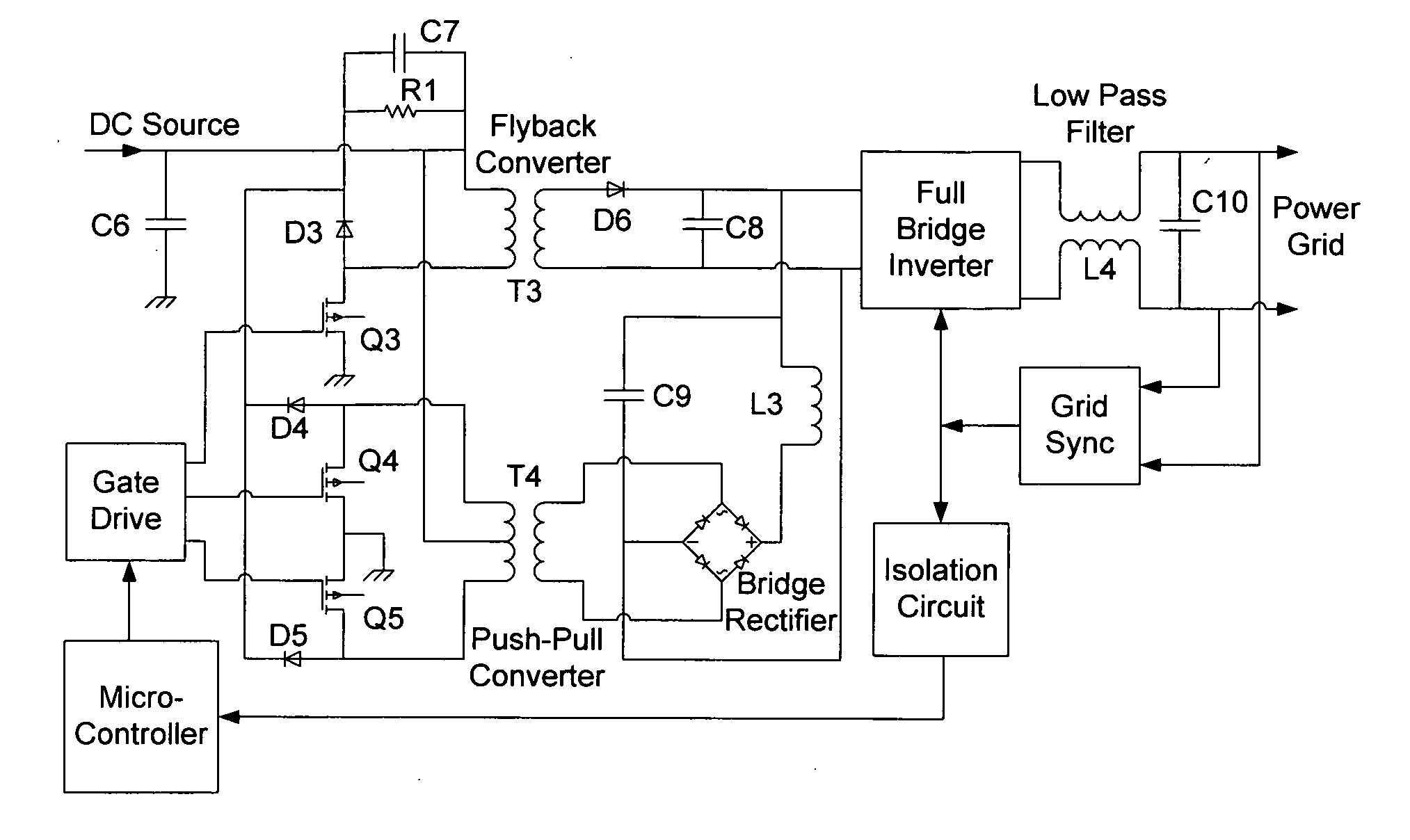
[0025]FIG. 3 demonstrates a circuit topology of the new hybrid converter micro-inverter design with the power outputs of the forward and flyback DC / DC converters are connected in series to a DC voltage bus.

[0026]FIG. 4 depicts a circuit topology of the new hybrid converter micro-inverter design with the power outputs of the forward and flyback DC / DC converters are connected in parallel to a DC voltage bus.

[0027]In these micro-inverter designs, the push-pull converter used a transformer with a turns ratio of 10 and a flyback transformer with a turns ratio of 3.5. Optimally, the passive clamping circuit can be replaced by an active clamping circuitry to re-circulate the energy in the push-pull and flyback converters when the power switching devices are turned off, in order to further increase the power conversion efficiency. The active clamping / energy recirculation...


PUM


Abstract

The present invention is a new design topology for solar/wind inverters using a new hybrid DC/DC converter design. This hybrid converter topology eliminates a difficult design compromise between lowering the minimum input voltage to harvest more solar/wind energy and achieving high power conversion efficiency when the input voltage is high in a conventional solar/wind inverter design. This invention uses both a forward converter and a flyback converter to deliver superior performance over a design that only uses one of the two converter topologies.

Description

BACKGROUND OF THE INVENTION[0001]As global concern for the environment and energy sustainability grows, the prevalence of solar power, wind power and other renewable energy sources has increased correspondingly. Solar power systems take up a great portion of this prevalence. It is primarily comprised of two components: photovoltaic (PV) panels and a power inverter. The solar panel harvests light energy and converts it into DC power which an inverter subsequently converts to usable AC power. Within the inverter, there are again two main sub-circuits, a DC / DC converter followed by a full-bridge inverter. The first DC / DC voltage converter converts the input DC power from the solar panel to a DC voltage that can be used by the subsequent inverter. The second part is a DC / AC inverter that converts the DC output of the converter to AC power compatible to the power grid.[0002]This invention is focused on the DC / DC converter that makes up the first half of the solar power inverter. The pres...

Claims


Application Information

Patent Timeline
IPC IPC(8): H02M5/45
CPCH02J3/381H02M7/4807H02M7/48
Inventor JIN, NORMAN LUWEIJIN, YIMENG
Owner JIN NORMAN LUWEI
Why Eureka
Try Eureka