Gas consuming system, fuel cell system and vehicle

a fuel cell system and gas consuming technology, applied in the field of gas consuming system, fuel cell system and vehicle, can solve the problems of further size reduction reduce achieve the reduction of the required capacity and size of the motor, reduce the size of the fuel cell system, and ensure the effect of sealing high reliability

Active Publication Date: 2012-07-19
TOYOTA JIDOSHA KK
View PDF4 Cites 7 Cited by
  • Summary
  • Abstract
  • Description
  • Claims
  • Application Information

AI Technical Summary

Benefits of technology

[0013]In the cooling system for cooling down the device by the circulation of the coolant, it is generally not required to significantly change the flow rate of the coolant circulation, although the flow rate of the coolant circulation may be somewhat varied according to the state of heat generation by the fuel cell. The coolant supply device is thus only required to cause the rotary member involved in the coolant circulation to be in the operating condition required for the coolant circulation. The gas supply device, on the other hand, generally requires compression of the gas, since the supply object is in the gas form. The gas supply device is thus required to drive the rotary member involved in both the gas compression and the pressure-feed of the gas at a relatively high speed.
[0014]In the fuel cell system according to the embodiment, simply driving the motor in the operating condition required for the coolant circulation enables the coolant supply device to have the operating condition required for the coolant circulation, while enabling the gas supply device to have the operating condition required for the oxidizing gas supply through the acceleration control. This does not require the high-speed operation of the motor for driving the gas supply device at a relatively high rotation speed and thereby does not require the high-capacity motor. This leads to reduction of the required capacity and size for the motor and further size reduction of the fuel cell system. The coolant supply device is only required to be driven in the operating condition sufficient for circulation of the coolant. This readily achieves the sealing property required for the coolant circulation path as well as the coolant supply device, thus ensuring the high reliability of sealing.
[0015]According to another embodiment, the fuel cell system may further include a casing with legs, wherein the motor and the gas supply device arranged to be opposed to each other across the transmission mechanism may be placed, along with the coolant supply device, in the casing, and the casing may be fastened to the fuel cell via the legs. This enables the heat generated by the fuel cell to be transmitted to the casing via the legs, which is advantageous for cooling down the fuel cell. The unitization of the components in the casing facilitates handling of the fuel cell system.
[0016]According to still another embodiment of the fuel cell system, an inner-casing flow path for the coolant may be formed in a motor surrounding wall of the casing surrounding the motor and arranged to pass through the coolant supply device. The motor can thus be externally cooled down by the flow of the coolant. This enhances the effectiveness to maintain the power of the motor and allows for simplification or even omission of the specific structure of the motor for ensuring the heat dissipation area, thus enabling size reduction of the motor.
[0017]According to another embodiment of the fuel cell system, the inner-casing flow path may have a plugged coolant outlet, which is located on an upper side of the casing in a state that the casing is installed at an installation position. Expelling the air bubbles entering the flow path in the cooling system through the coolant outlet and subsequently plugging the coolant outlet ensures the supply and circulation of the coolant with substantially no air bubbles. This reduces the potential pressure loss due to the remaining air bubbles during supply and circulation of the coolant and ensures the stable supply of the coolant. For example, the coolant should be replaced, when the ion dissolution into the coolant increases the ion conductivity of the coolant. The air bubbles entering the flow path during replacement of the coolant can readily be expelled in the above manner.
[0018]One aspect of a vehicle, on which the fuel cell system according to any of the above embodiments is mounted, wherein the motor driveshaft of the motor, a rotating shaft of the coolant supply device and a rotating shaft of the gas supply device are arranged across a vehicle width direction to be parallel to one another, and the fuel cell, the motor, the coolant supply device and the gas supply device are placed in a hood lower region below a hood of the vehicle.

Problems solved by technology

This problem is not characteristic of the fuel cell system but is commonly found in gas consuming systems including gas consuming devices that require cooling.
This leads to reduction of the required capacity and size for the motor and further size reduction of the fuel cell system.

Method used


Image

  • Gas consuming system, fuel cell system and vehicle
  • Gas consuming system, fuel cell system and vehicle
  • Gas consuming system, fuel cell system and vehicle

Examples


Embodiment Construction

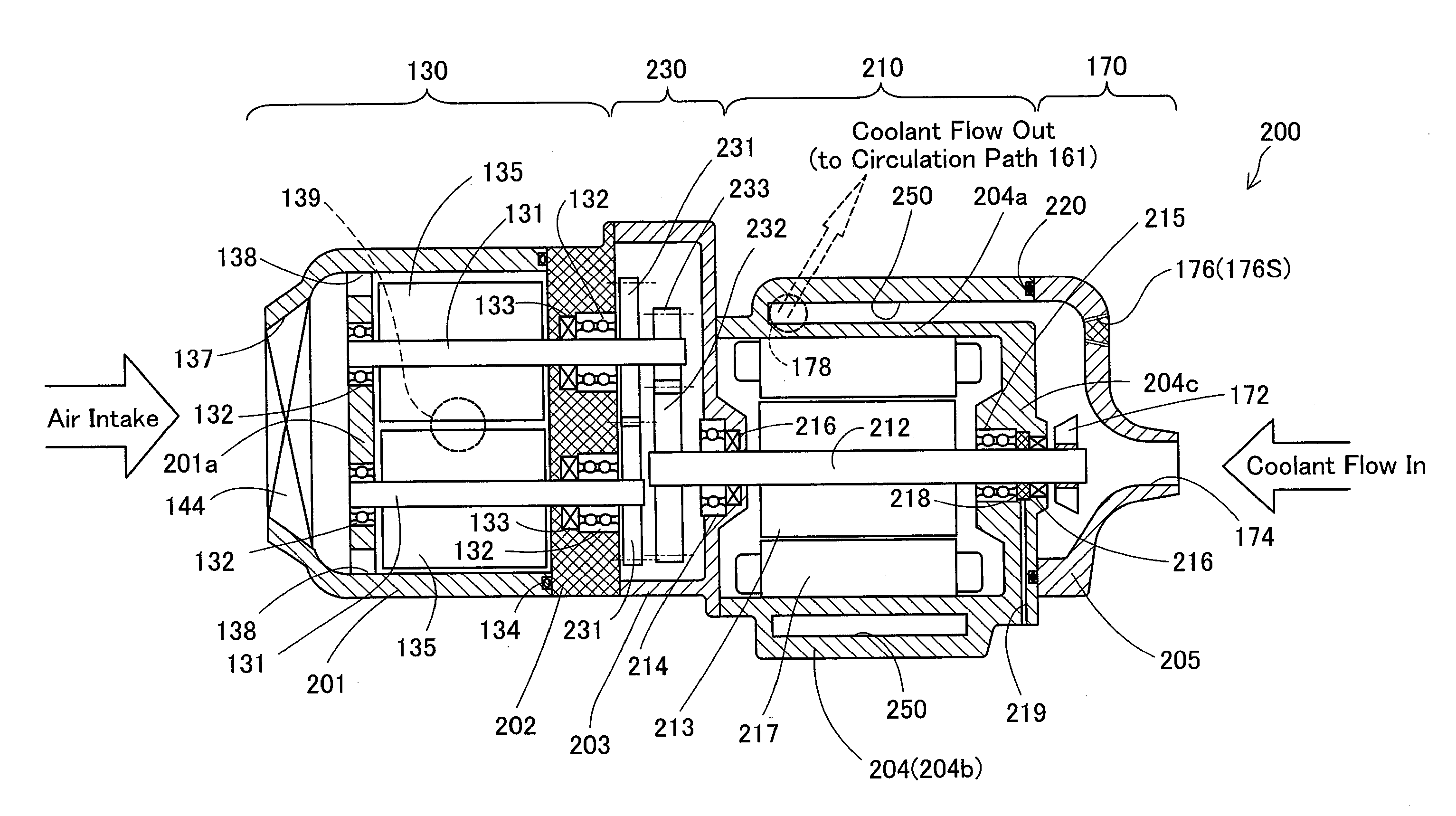
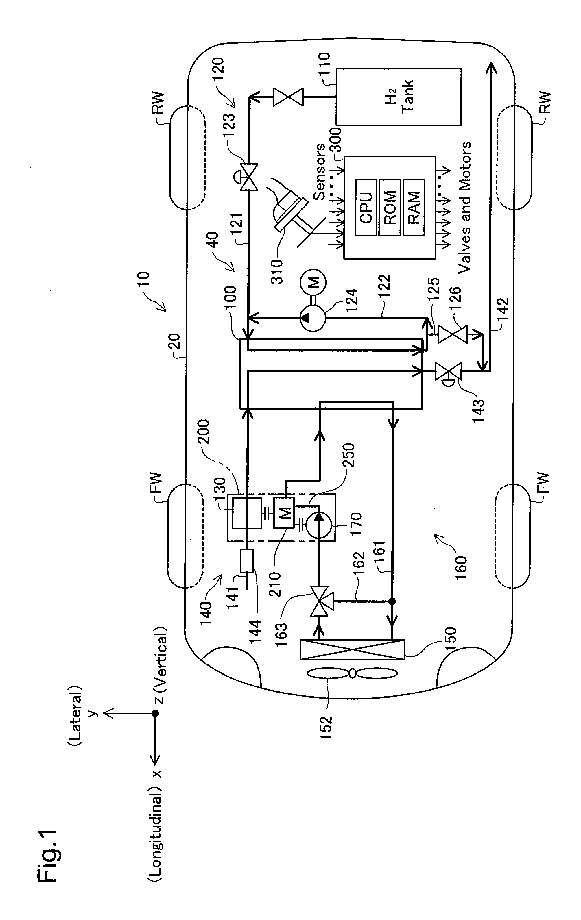
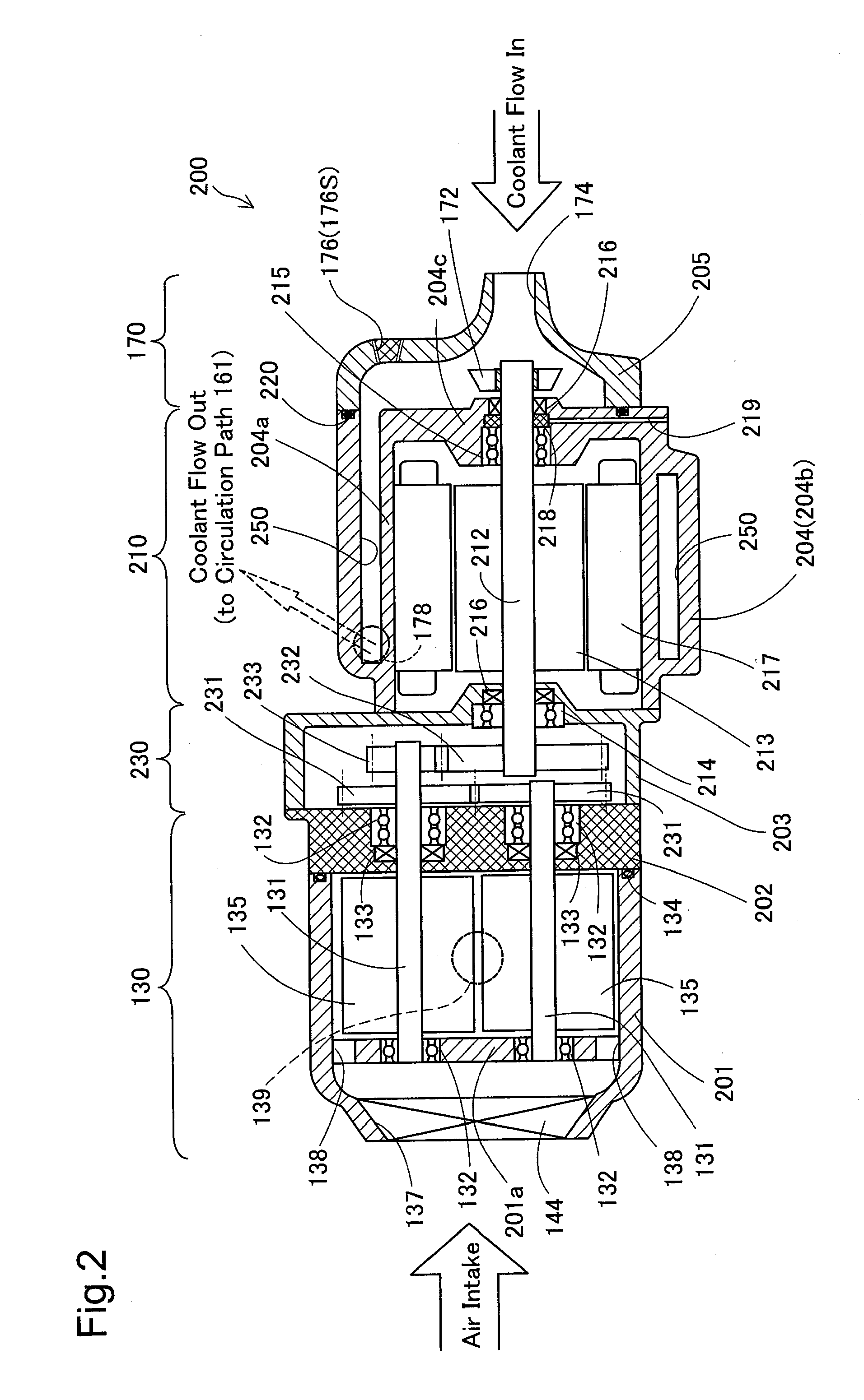
[0033]Aspects of the present invention are described in detail with reference to embodiments. FIG. 1 is a plan view schematically illustrating a fuel cell vehicle 10 according to one embodiment of the invention.

[0034]As illustrated, the fuel cell vehicle 10 has a fuel cell system 40 mounted on a vehicle body 20. The fuel cell system 40 has a fuel cell 100, a hydrogen gas supply system 120 including a hydrogen gas tank 110, an air supply system 140 including a compressor 130, and a cooling system 160 including a radiator 150 and a′fan 152. The fuel cell 100 is constructed by stacking power generation modules including membrane electrode assemblies (MEAs) (not shown), each of which is obtained by joining two electrodes, i.e., anode and cathode, to both faces of an electrolyte membrane, and is located in a hood lower region of the vehicle body 20. The installation positions of the fuel cell and the relevant components including the compressor 130 will be described later. The fuel cell ...


PUM

PropertyMeasurementUnit
forceaaaaaaaaaa
driving forceaaaaaaaaaa
electric poweraaaaaaaaaa

Abstract

In a fuel cell system, a compressor used for supply of a gas and a motor are arranged to be opposed to each other across a transmission mechanism, such that a motor driveshaft is placed to face rotating shafts of the compressor. Such opposed arrangement enables the motor and the compressor to be relatively close to each other across only a narrow distance required for the transmission mechanism. Additionally, a circulation pump used for supply of a coolant is placed, such that the motor driving force is transmitted from the motor driveshaft to the circulation pump directly or via the transmission mechanism.

Description

BACKGROUND[0001]1. Technical Field[0002]The present invention relates to a gas consuming system including a gas consuming device that consumes supplied gas, a fuel cell system including a fuel cell that generates electric power while consuming supplied fuel gas and oxidizing gas, and a vehicle equipped with the fuel cell system.[0003]2. Background Art[0004]In a fuel cell as one typical example of the gas consuming device that consumes supplied gas, for example, in a polymer electrolyte fuel cell, reactive gases (fuel gas an oxidizing gas, e.g., the air) are supplied to a pair of electrodes (anode and cathode) arranged across an electrolyte membrane. The fuel cell generates electric power, as the electrochemical reaction proceeds with consuming the supplied reactive gases. The continuous gas supply according to the power demand is essential for the progress of the electrochemical reaction. This electrochemical reaction is an exothermic reaction, so that it is generally required to co...

Claims


Application Information

Patent Timeline
Patent Type & Authority Applications(United States)
IPC IPC(8): B60K1/04B60L11/18H01M8/04
CPCB60K11/02B60K2001/0411B60K2015/03315Y02T90/34H01M8/04089H01M8/04201Y02E60/50H01M8/04029Y02T90/40
Inventor MASAKI, I, DAISUKE
Owner TOYOTA JIDOSHA KK
Why Eureka
Try Eureka