Circuit simulation model of capacitor, constructing method of simulation model, method of circuit simulation, circuit simulator

a capacitor and simulation model technology, applied in the field of circuit simulation model, capacitor simulation model, circuit simulation model, constructing method of simulation model, etc., can solve the problems of incomplete failure of electronic device design, difficult to obtain highly accurate spice model, and complicated frequency characteristics of capacitor impedance and more particularly frequency characteristics in high-frequency bands, etc., to achieve accurate and suitable implementation of circuit design and accurate representation of characteristics

Active Publication Date: 2012-07-19
TAIYO YUDEN KK
View PDF0 Cites 19 Cited by
  • Summary
  • Abstract
  • Description
  • Claims
  • Application Information

AI Technical Summary

Benefits of technology

[0010]However, the above-mentioned background art has the following disadvantages. First, the equivalent circuit described in Non-Patent Document 1 has frequency-dependent circuit elements, and therefore, the circuit cannot be incorporated into a SPICE simulator directly. Before incorporating this equivalent circuit into a SPICE simulator, the values of the circuit elements that change due to frequency, temperature, and DC bias need to be calculated for different frequencies, temperatures and DC biases using MathCad by Mathsoft, and thereafter an ASCII table (a table showing a relationship between circuit elements and frequencies, temperatures, and voltages) needs to be generated. This makes the equivalent circuit very inconvenient to use.
[0013]The present invention was made in view of these problems, and it is an object of the present invention to accurately represent characteristics changes caused by a DC bias of a capacitor. Another object of the present invention is to suitably perform a simulation of a circuit including a capacitor with a DC bias applied thereto.
[0019]According to the present invention, a calculation circuit to solve a circuit equation is constructed by configuring a basic equivalent circuit for a capacitor and replacing circuit elements included in the basic equivalent circuit with nonlinear voltage dependent voltage sources. This makes it possible to accurately represent the characteristics of a capacitor having a DC bias applied thereto, thereby realizing an accurate and suitable implementation of circuit design and the like of electronic devices that use capacitor products.

Problems solved by technology

Due to the presence of various parasitic parameters, frequency characteristics of the impedance of a capacitor and more particularly the frequency characteristics in a high-frequency band become considerably complicated.
This makes it very difficult to obtain a highly accurate SPICE model.
Therefore, if circuit analysis or design is performed by using an equivalent circuit with a nominal capacitance value or without a DC bias, it is inevitable that the results thereof greatly differ from the actual circuit characteristics, which may lead to a complete failure of the design of the electronic device.

Method used


Image

  • Circuit simulation model of capacitor, constructing method of simulation model, method of circuit simulation, circuit simulator
  • Circuit simulation model of capacitor, constructing method of simulation model, method of circuit simulation, circuit simulator
  • Circuit simulation model of capacitor, constructing method of simulation model, method of circuit simulation, circuit simulator

Examples


embodiment 1

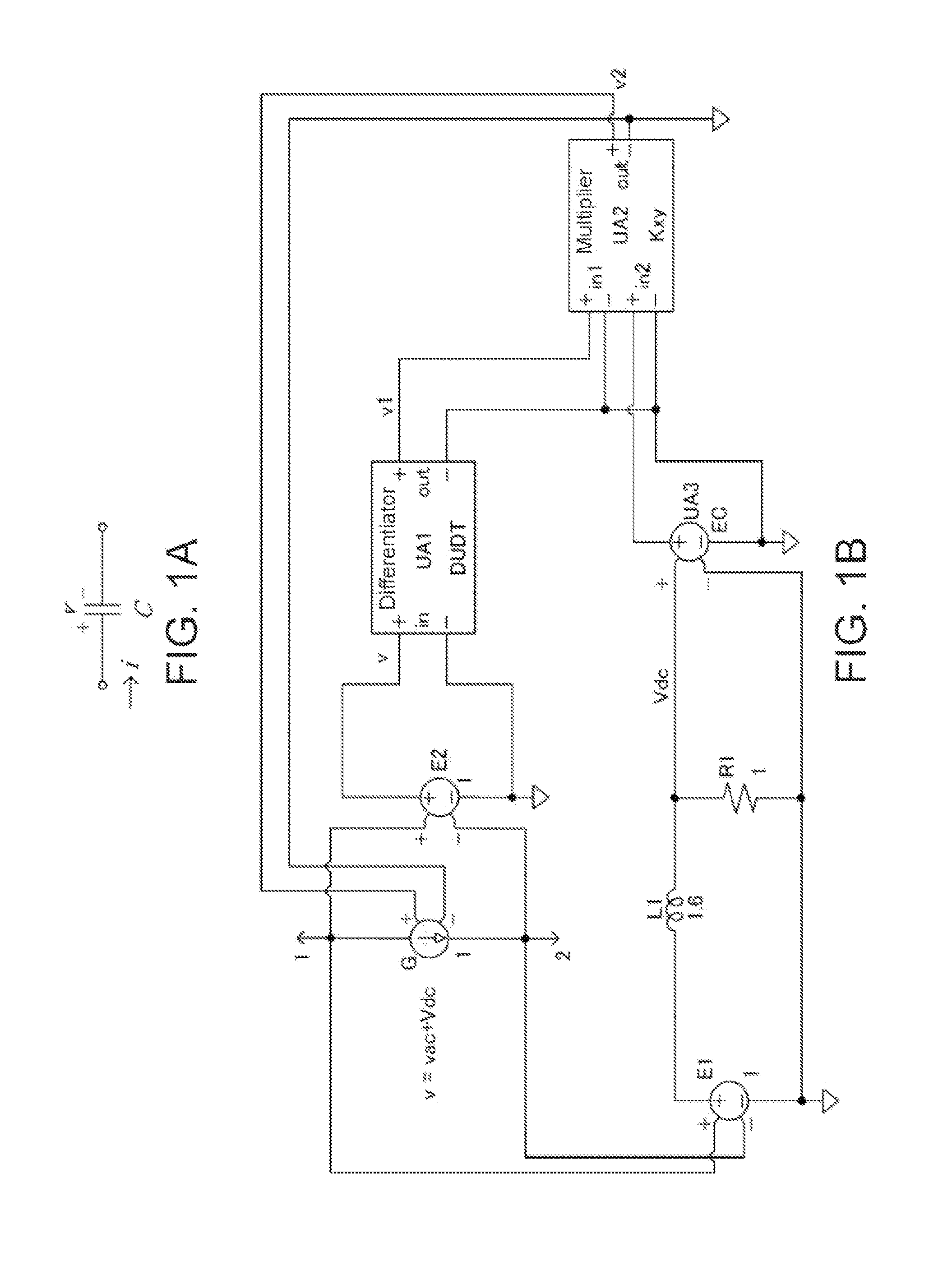
[0049]First, the case of the idealized C circuit model will be explained. As shown in FIG. 1A, in the idealized C circuit model of the capacitor, an equivalent circuit is constituted of one circuit element, which is a capacitance element C. Generally, a nominal capacitance is used in this case. In the same figure, “v” denotes a total voltage applied across the capacitor, which equals a voltage across both ends of the capacitance element C. A current through the capacitor is denoted by “i”, which equals a current through the capacitance element C. The impedance characteristics represented by the idealized C circuit differ so significantly, especially in a high frequency band, from those in an actual product that the model cannot be suitably used for a circuit design and simulation. However, the idealized C circuit model can be conveniently used in an early stage of the circuit design or for predicting the circuit characteristics.

[0050]The voltage “v” applied across the capacitance el...

embodiment 2

[0091]Next, the case of an RC circuit model will be explained. When the loss due to a resistance needs to be taken into account, a series resistance is added to the idealized C circuit. FIG. 3A shows a circuit configuration of the RC circuit model. A capacitance element C is a nominal capacitance. A resistance element R is derived from a dielectric loss tangent Tan δ that is obtained by the same measurement frequency and measurement voltage as those of the idealized C circuit. This equivalent circuit has the same level of accuracy as that of the idealized C circuit model, and is only used in an early stage of circuit design or for predicting circuit characteristics. In FIG. 3A, VC denotes a voltage applied across the capacitance element C. VR denotes a voltage applied across the resistance element R, and “i” denotes a current through the capacitor. The total voltage V applied to the capacitor is equal to the sum of the aforementioned VC and VR, which is expressed by the following Fo...

embodiment 3

[0117]Next, the case of an RLC circuit model will be explained. When the parasitic inductance of the capacitor needs to be taken into account in the above-mentioned RC circuit, an RLC series circuit shown in FIG. 4A is used as an equivalent circuit for the capacitor. The RLC series circuit is the most fundamental and most commonly used equivalent circuit for a capacitor. Because the parasitic inductance is taken into account, frequency characteristics of the impedance of the capacitor, more particularly frequency characteristics of the resonance, are improved in this circuit. In FIG. 4A, vC, vL, and vR respectively denote voltages of the capacitance element C, the parasitic inductance L, and the resistance element R that are connected in series, and “i” denotes a current through the capacitor. The total voltage “v” applied across the capacitor equals the sum of these vC, vL, and vR, and is expressed by the following Formula 31.

v=vc+vL+vR=vac+Vdc  Formula 31

[0118]Characteristics of t...


PUM


Abstract

Provided is a circuit simulation model that can suitably represent capacitor characteristics, thereby realizing accurate circuit design and circuit analysis. A SPICE model is constituted of a capacitor unit in which a capacitor is replaced with a linear voltage dependent current source, a low-pass filter unit that has a function of extracting a DC bias voltage, a calculation circuit unit that is configured by combining an adder, a multiplier, and the like to perform a calculation of a circuit equation derived from an equivalent circuit for a capacitor such as an idealized C circuit model, an RC circuit model, or the like, and a linear voltage dependent voltage source that applies a total voltage applied across the capacitor to the calculation circuit.

Description

[0001]This application claims the benefit of Japanese Application No. 2011-007389, filed in Japan on Jan. 17, 2011, which is hereby incorporated by reference in its entirety.[0002]This application also hereby incorporates by reference U.S. patent application Ser. No. 13 / 160,394 in its entirety.TECHNICAL FIELD[0003]The present invention relates to a circuit simulation model for a capacitor with a DC bias applied thereto, a constructing method of the simulation model, a circuit simulation method, and a circuit simulator, and more particularly, to a circuit simulation model for a capacitor that is suitable for a simulation with a SPICE simulator, a constructing method of the simulation model, a circuit simulation method, and a circuit simulator.BACKGROUND ART[0004]Capacitors are one of the most fundamental electronic components (circuit elements) in an electronic circuit system, and are widely used in various electronic devices. Use of a computer simulation for precise analysis and des...

Claims


Application Information

Patent Timeline
Patent Type & Authority Applications(United States)
IPC IPC(8): G06F17/50
CPCG06F17/5036G06F30/367
Inventor WU, XIANGYING
Owner TAIYO YUDEN KK
Why Eureka
Try Eureka