
Aircraft motor drive control apparatus and aircraft motor drive control system

Active Publication Date: 2012-07-26
NABLESCO CORP
View PDF1 Cites 11 Cited by
  • Summary
  • Abstract
  • Description
  • Claims
  • Application Information

AI Technical Summary

Benefits of technology

[0010]Further, the required operating condition of a device installed in an aircraft changes due to not only a situation where the flight condition of the aircraft is stable, but also various situations, including, for example, a situation where the flight condition of the aircraft changes suddenly due to the weather or the state of air currents, a situation where the aircraft performs the takeoff operation or the landing operation, and a situation where an unexpected trouble has occurred. Therefore, it is desired that a motor drive control apparatus that performs a drive control of a motor for driving a device for which the operating condition changes depending on the situation of the aircraft in this way can efficiently ensure control performance and suppress heat generation on a higher level in a well-balanced manner.
[0011]In view of the foregoing circumstances, it is an object of the present invention to provide an aircraft motor drive control apparatus and an aircraft motor drive control system that can be used for the drive control of a motor for driving a device for which the required operating condition changes depending on the situation of an aircraft and that can efficiently ensure control performance and suppress heat generation on a high level in a well-balanced manner.
[0014]When the first PWM frequency command signal is received, the PWM frequency is controlled in the aircraft motor drive control apparatus such that an asynchronous PWM control is performed at a PWM frequency of a predetermined constant frequency. Accordingly, the predetermined constant frequency is set to a high frequency, and therefore it is possible to ensure sufficient control performance, and increase the response of the motor as appropriate according to the situation of the aircraft. On the other hand, when the second PWM frequency command signal is received, the PWM frequency is controlled in the aircraft motor drive control apparatus at a PWM frequency in a frequency range lower than the above-described predetermined constant frequency. Accordingly, the PWM frequency is set to a low frequency when there is less demand on higher response of the motor, and therefore it is possible to reduce the loss of the switching element as appropriate according to the situation of the aircraft within the range in which control performance can be ensured, thus suppressing heat generation. Furthermore, when the second PWM frequency command signal is received, the PWM frequency is controlled in the aircraft motor drive control apparatus such that an asynchronous PWM control is performed if the motor has a rotational speed less than a predetermined rotational speed and that a synchronous PWM control is performed if the motor has a rotational speed greater than or equal to the predetermined rotational speed. Accordingly, even if there is less demand on higher response of the motor, it is possible to ensure the performance of controlling the motor as appropriate according to the rotational speed of the motor, while achieving balance with the suppression of heat generation.
[0015]Therefore, with the above-described configuration, it is possible to provide an aircraft motor drive control apparatus that can be used for drive control of a motor that drives a device for which the required operating condition changes depending on the situation of an aircraft and that can ensure control performance and suppress heat generation on a high level in a well-balanced manner.
[0017]With this configuration, the controller can also transmit, as the PWM frequency command signal, the third PWM frequency command signal depending on the situation of the aircraft, in addition to the first PWM frequency command signal and the second PWM frequency command signal. Also, when the third PWM frequency command signal is received, the aircraft motor drive control apparatus outputs the high-PWM frequency command signal if the speed change rate value is greater than or equal to the predetermined determination value and outputs the low-PWM frequency command signal if the speed change rate value is less than the predetermined determination value. Accordingly, it is possible to increase the response of the motor as appropriate when the degree of change in the rotational speed of the motor is large. When the degree of change in the rotational speed of the motor is small, it is possible to reduce the loss of the switching element as appropriate according to the situation of the aircraft within the range in which control performance can be ensured, thus suppressing heat generation.
[0019]With this configuration, it is possible to provide an aircraft motor drive control system that can be used for drive control of a motor that drives a device for which the required operating condition changes depending on the situation of an aircraft and that can ensure control performance and suppress heat generation on a higher level in a well-balanced manner.

Problems solved by technology

Therefore, it is difficult to achieve this to a satisfying level with a configuration as that of the motor drive control apparatus disclosed in JP 2010-57243A, in which the PWM frequency is controlled by selecting a synchronous PWM control or one of a synchronous PWM control and an asynchronous PWM control according to whether the current supplied to the motor or the generated torque is greater or smaller than a threshold.
Further, the required operating condition of a device installed in an aircraft changes due to not only a situation where the flight condition of the aircraft is stable, but also various situations, including, for example, a situation where the flight condition of the aircraft changes suddenly due to the weather or the state of air currents, a situation where the aircraft performs the takeoff operation or the landing operation, and a situation where an unexpected trouble has occurred.

Method used


Image

  • Aircraft motor drive control apparatus and aircraft motor drive control system
  • Aircraft motor drive control apparatus and aircraft motor drive control system
  • Aircraft motor drive control apparatus and aircraft motor drive control system

Examples


Embodiment Construction

[0028]Hereinafter, an embodiment for carrying out the present invention will be described with reference to the accompanying drawings. Note that the embodiment of the present invention is widely applicable as an aircraft motor drive control apparatus and an aircraft motor drive control system that drive a motor mounted to an aircraft for driving a device installed in the aircraft and that control the operational status of the motor.

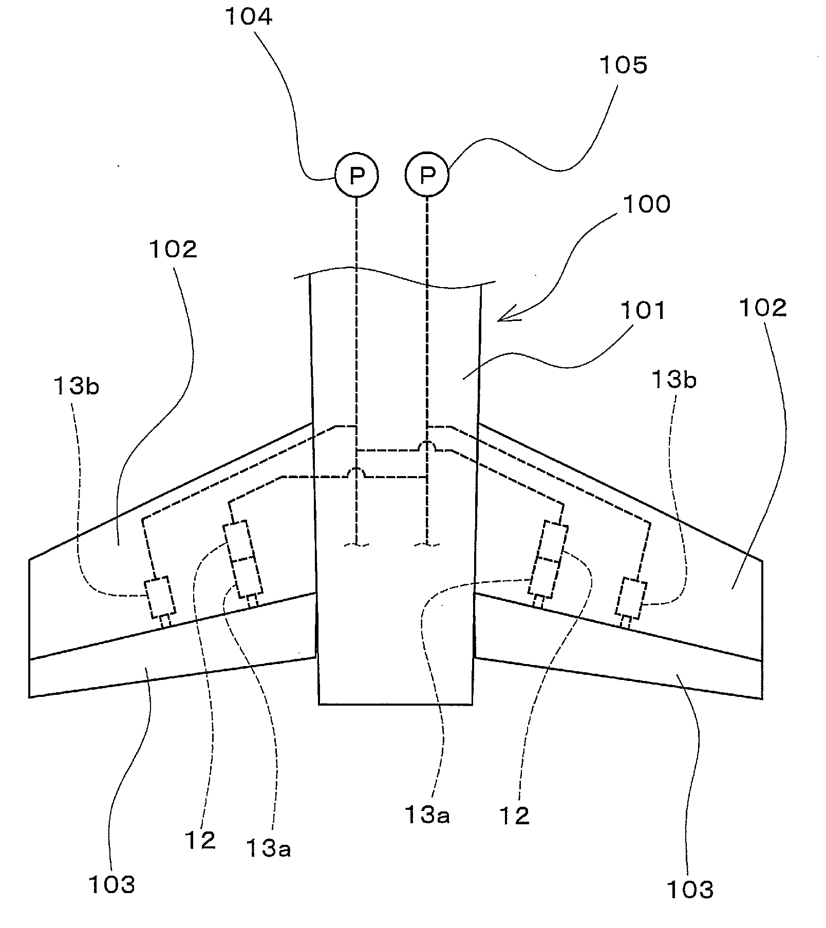
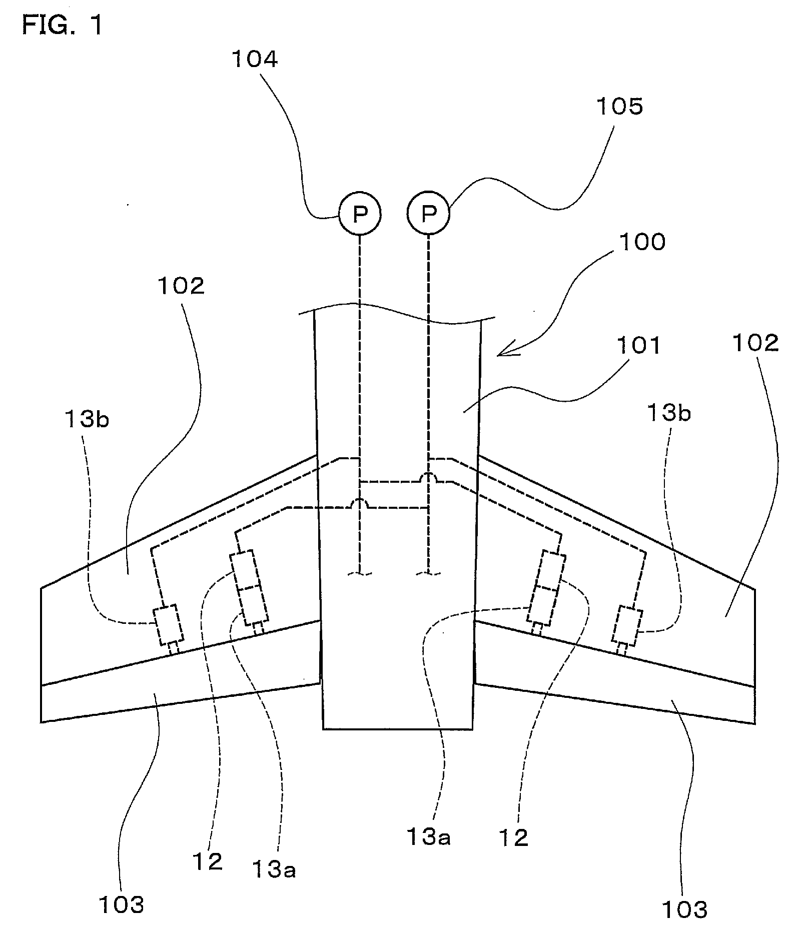
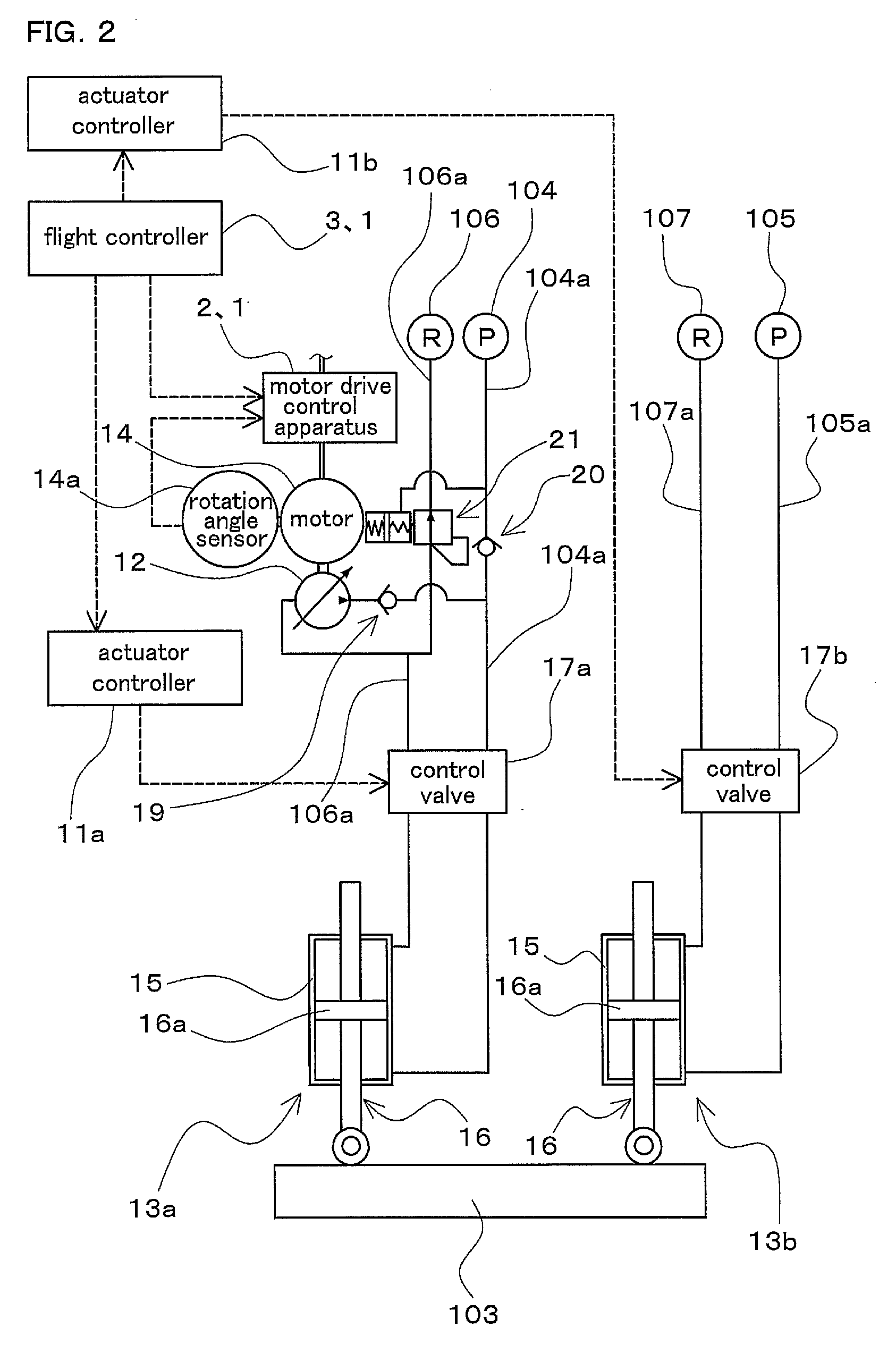
[0029]FIG. 1 is a diagram showing part of an aircraft 100 in which is installed a backup hydraulic pump 12 as an exemplary device to which an aircraft motor drive control apparatus and an aircraft motor drive control system according to one embodiment of the present invention are applied. Note that FIG. 1 shows part of the rear portion of a body 101 of the aircraft 100 and a pair of tailplanes (102), and illustration of a vertical tail at the rear part of the body 101 is omitted. FIG. 2 is a diagram schematically showing an aircraft motor drive control sy...


PUM


Abstract

The command signal processing unit outputs, when a first PWM frequency command signal is received, a high-PWM frequency command signal such that an asynchronous PWM control is performed at a PWM frequency of a predetermined constant frequency. The command signal processing unit outputs, when a secondPWM frequency command signal is received, a low-PWM frequency command signal such that an asynchronous or synchronous PWM control is performed at a frequency lower than the above-described frequency. The PWM frequency control unit controls the PWM frequency such that an asynchronous PWM control is performed if a motor has a rotational speed less than a predetermined rotational speed and that a synchronous PWM control is performed if the motor has a rotational speed greater than or equal to the predetermined rotational speed, when a low-PWM frequency command signal is input.

Description

CROSS-REFERENCE TO RELATED APPLICATIONS[0001]This application claims priority to Japanese Patent Application No. 2011-009457. The entire disclosure of Japanese Patent Application No. 2011-009457 is hereby incorporated herein by reference.BACKGROUND OF THE INVENTION[0002]1. Field of the Invention[0003]The present invention relates to an aircraft motor drive control apparatus and an aircraft motor drive control system that drive a motor mounted to an aircraft for driving a device installed in the aircraft and that control the operational status of the motor.[0004]2. Description of Related Art[0005]Various electrically powered devices are installed in an aircraft, and such devices are driven by motors (electric motors) mounted to the aircraft. Examples of the aforementioned devices include an electrically powered hydraulic pump for supplying pressure oil to a hydraulically operated actuator for driving control surfaces that are formed as moving surfaces (flight control surfaces) and ar...

Claims


Application Information

Patent Timeline
IPC IPC(8): H02P6/20H02P6/06H02P6/08H02P6/17H02P6/28
CPCG05B19/414H02P27/085H02P27/08G05B2219/42239B64C13/40B64C13/505
Inventor TSUNEMATSU, TOKUJINAKAJIMA, KAZUSHIGEKITAZWA, HIROYUKIYOKOGAWA, TOMOYUKI
Owner NABLESCO CORP
Features
  • Generate Ideas
  • Intellectual Property
  • Life Sciences
  • Materials
  • Tech Scout
  • Unparalleled Data Quality
  • Higher Quality Content
  • 60% Fewer Hallucinations
Learn More