Method and Apparatus for Removing Low-Concentration Methane

a low-concentration, methane technology, applied in the direction of separation processes, physical/chemical process catalysts, combustion types, etc., can solve the problems of significant safety concerns, difficult oxidization removal of methane at low temperatures of 400° c, and inability to process, so as to reduce the capacity of heat exchangers, improve economic performance, and prevent activity inhibition good

Active Publication Date: 2012-07-26
OSAKA GAS CO LTD
View PDF0 Cites 25 Cited by
  • Summary
  • Abstract
  • Description
  • Claims
  • Application Information

AI Technical Summary

Benefits of technology

[0098]With the methane removing method of the present invention, it is possible to employ a catalyst having a very good resistance against activity inhibition due to sulfur compounds. Therefore, even in the presence of various sulfur compounds. (hydrosulfide, methyl mercaptan, dimethyl sulfide, sulfur oxide, etc.), the methane removal is possible from such low temperature as about 350° C. Accordingly, in comparison with the conventional technique, it is possible to reduce the capacity of the heat exchanger, so that the economic performance can be improved significantly. Further, with the methane removing method of the present invention, it is possible to keep the catalyst outlet temperature 550° C. or lower constantly even in the event of sudden sharp variation in the methane concentration in the treatment-object gas. Therefore, the durability of the catalyst can be ensured and stable methane removal performance can be obtained for an extended period of time. In addition, as there arises no need of using expensive materials for the pining, the heat exchanger, the economic performance can be improved significantly.

Problems solved by technology

Hence, there is a significant concern about safety and the process is not feasible.
So, with the above-described catalysts, oxidization removal of methane is difficult at low temperatures of 400° C. or lower.
In order to preheat coal mine ventilation gas at ambient temperature and in a great amount thereof, a heat exchanger with a large capacity is required, so there arises the problem of inferior economic performance.
Further, in case the catalyst inlet temperature is about 500° C., with addition of reaction heat generated from oxidization of methane, the catalyst outlet temperature becomes from 600° C. to 700° C. This is not only detrimental to the durability of catalyst, but also causes another problem of additional costs of piping and the heat exchanger due to heat resistant temperature requirement.
Due to sulfur compounds present in coal, coal mine ventilation gas contains trace amounts of sulfur compounds (hydrosulfide, methyl mercaptan, dimethyl sulfide, sulfur oxide, etc.) These are strong catalyst poisons, which makes catalytic oxidization of methane at low temperatures even more difficult.
Further, the concentration of methane present in the coal mine ventilation gas varies widely from 0.1 to 1% and also prediction of its variation behavior is difficult.
So, with simple use of a heat exchanger and a catalyst in combination, the gas temperature at the catalyst inlet will be reduced so that sufficient removal performance cannot be obtained.
Conversely, in the event of sharp rise in the methane concentration, there occurs a sharp and sudden rise in the catalyst layer temperature within a short period of time, which leads to irreversible deterioration of catalyst activity.
As a result, there occurs a sharp rise in the catalyst layer temperature within a short period of time, which may invite fatal destruction of the catalyst and / or the heat exchanger.
However, as this method requires fuel for the burner, the running cost increases.
Further, the method involves a process in which as the methane concentration increases, the catalyst outlet temperature rises, which in turn leads to rise of the catalyst inlet temperature.
As a result, in the event of sudden and rapid variation in the methane concentration, deterioration of catalyst activity is unavoidable.

Method used


Image

  • Method and Apparatus for Removing Low-Concentration Methane
  • Method and Apparatus for Removing Low-Concentration Methane
  • Method and Apparatus for Removing Low-Concentration Methane

Examples


first embodiment

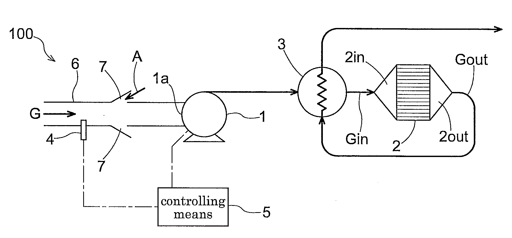
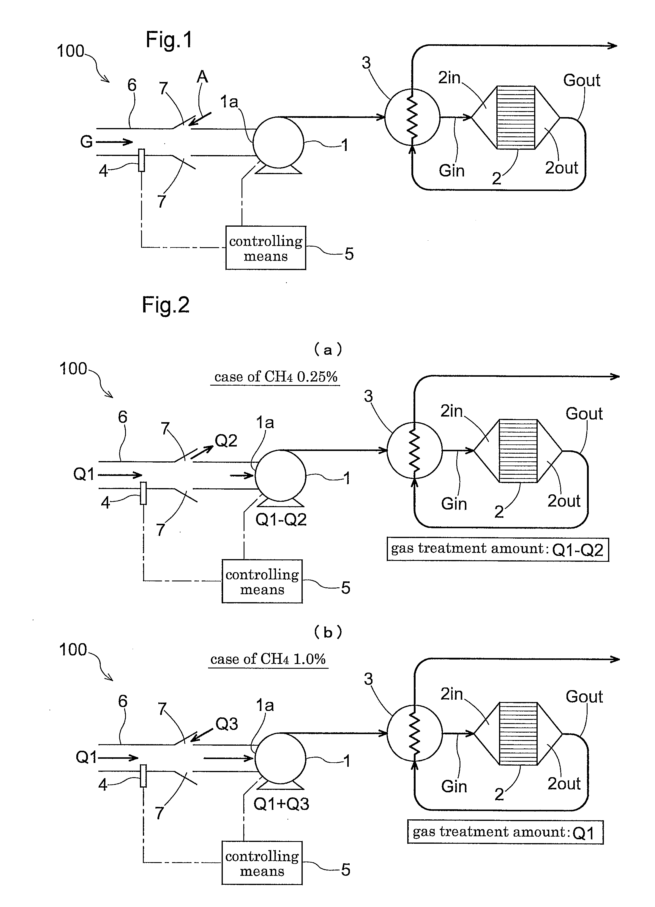
[0117]A low concentration methane removing apparatus 100 according to the present invention includes a blower 1 for introducing a treatment-object gas G to the apparatus 100, an oxidization catalyst 2 for contact-oxidizing methane (FIG. 1 shows a condition where the oxidization catalyst is accommodated within a treatment cylinder), a heat exchanger 3 for effecting heat exchange between gases Gin, Gout before and after passage through the oxidization catalyst 2, a methane concentration detecting means 4 disposed upstream of the oxidization catalyst 2, and a controlling means 5 for controlling a blowing rate of the blower 1 in accordance with a detection value of the detecting means 4. Upstream of a suction inlet 1a of this blower 1, there is provided a suction pipe 6 for drawing in an amount of treatment-object gas G from a suctioning portion; and between an outlet of this suction pipe 6 and the suction inlet 1a of the blower 1, there is provided a ventilation portion 7 providing a c...

second embodiment

[0149]As shown in FIG. 11, the methane oxidization removing apparatus 100 of the invention can be provided, if needed, with a flow amount distributing means 201 and a pipe 202 for refluxing a portion of the exhaust gas from the apparatus outlet side to the apparatus inlet side.

[0150]With co-utilization of this method of refluxing a portion of the exhaust gas from the apparatus outlet side to the apparatus inlet side, even when the methane concentration is about 1.2%, it is still possible to maintain the catalyst outlet temperature at 550° C. or lower and the catalyst inlet temperature at 350° C. or higher.

modified embodiments of first and second embodiments

[0151](1) In the foregoing embodiments, the blower was provided at the inlet of the apparatus. However, it does not matter as long as this blower is capable of introducing the treatment-object gas to the oxidization catalyst. So, it is possible to configure such that the blower is disposed not at the inlet but at the outlet of the apparatus thereby to establish a negative pressure inside the apparatus relative to the atmospheric pressure.

[0152](2) Preferably, the methane concentration detecting means should be disposed in close vicinity of the inlet of the apparatus from the viewpoint of detecting variation in the methane concentration as quickly as possible and this detecting means should be disposed within the suction pipe from the viewpoint of detecting the methane concentration of the treatment-object gas. However, in the construction of the present invention, as the treatment-object gas amount and the air amount are determined in accordance with the blowing rate of the blower, ...


PUM

PropertyMeasurementUnit
temperatureaaaaaaaaaa
temperaturesaaaaaaaaaa
temperatureaaaaaaaaaa

Abstract

Disclosed are a method and an apparatus for removing methane from a gas which contains the methane at such a low concentration as not to be rendered into a combustible range with whatever ratio of air mixed therewith. In order to ensure satisfactory methane removal performance even in the coexistence of sulfur compound and in order also to provide stable methane removal performance for an extended period of time without performance deterioration even when the methane concentration varies significantly, the gas is fed to a heat exchanger for preheating and methane is exposed to an oxidation catalyst which oxidizes the methane through contact therewith. Then, the resultant gas is fed again to the heat exchanger for heat recovery through heat exchange with un-reacted gas. Further, the flow rate of gas to be treated is varied, according to a concentration of the methane contained in this treated gas.

Description

TECHNICAL FIELD[0001]The present invention relates to a method and an apparatus for removing methane from a gas such as a coal mine ventilation gas that contains methane at such a low concentration which is lower than a lower limit of the combustion limit (explosion limit) of methane and which is too low to be rendered into its combustible range with whatever ratio of air mixed therewith.BACKGROUND ART[0002]A bed of coal contains a great amount of methane adsorbed therein and an effective utilization thereof is now underway. Methane collected from an un-mined coal bed by e.g. drainage has a relatively high methane concentration ranging from 30% to 95%. Hence, its effective utilization is relatively easy through concentration or the like. Whereas, a gas discharged through ventilation of a coal mine has only a low concentration of methane ranging from 0.1 to 1%, so that most of it is discharged into the atmosphere. Although methane is not harmful for human bodies, it provides a high g...

Claims


Application Information

Patent Timeline
Patent Type & Authority Applications(United States)
IPC IPC(8): B01D53/72B01D53/86
CPCB01D53/8668Y02C20/20B01D2255/1021B01D2255/1028B01D2255/20707B01D2255/20715B01D2257/7025B01D2259/65B01J21/063B01J21/066B01J23/42B01J23/468B01J35/04F23G5/46F23G5/50F23G7/07F23G2206/10B01D2251/11
Inventor OHTSUKA, HIROFUMISAKAI, TSUTOMU
Owner OSAKA GAS CO LTD
Why Eureka
Try Eureka