
Commutating Circuit Breaker

a circuit breaker and circuit technology, applied in the direction of air breakers, high-tension/heavy-dress switches, contacts, etc., can solve the problems of increased burden, impracticality large, and physical separation of electrodes

Inactive Publication Date: 2012-08-09
INNOLITH ASSESTS AG
View PDF5 Cites 41 Cited by
  • Summary
  • Abstract
  • Description
  • Claims
  • Application Information

AI Technical Summary

Benefits of technology

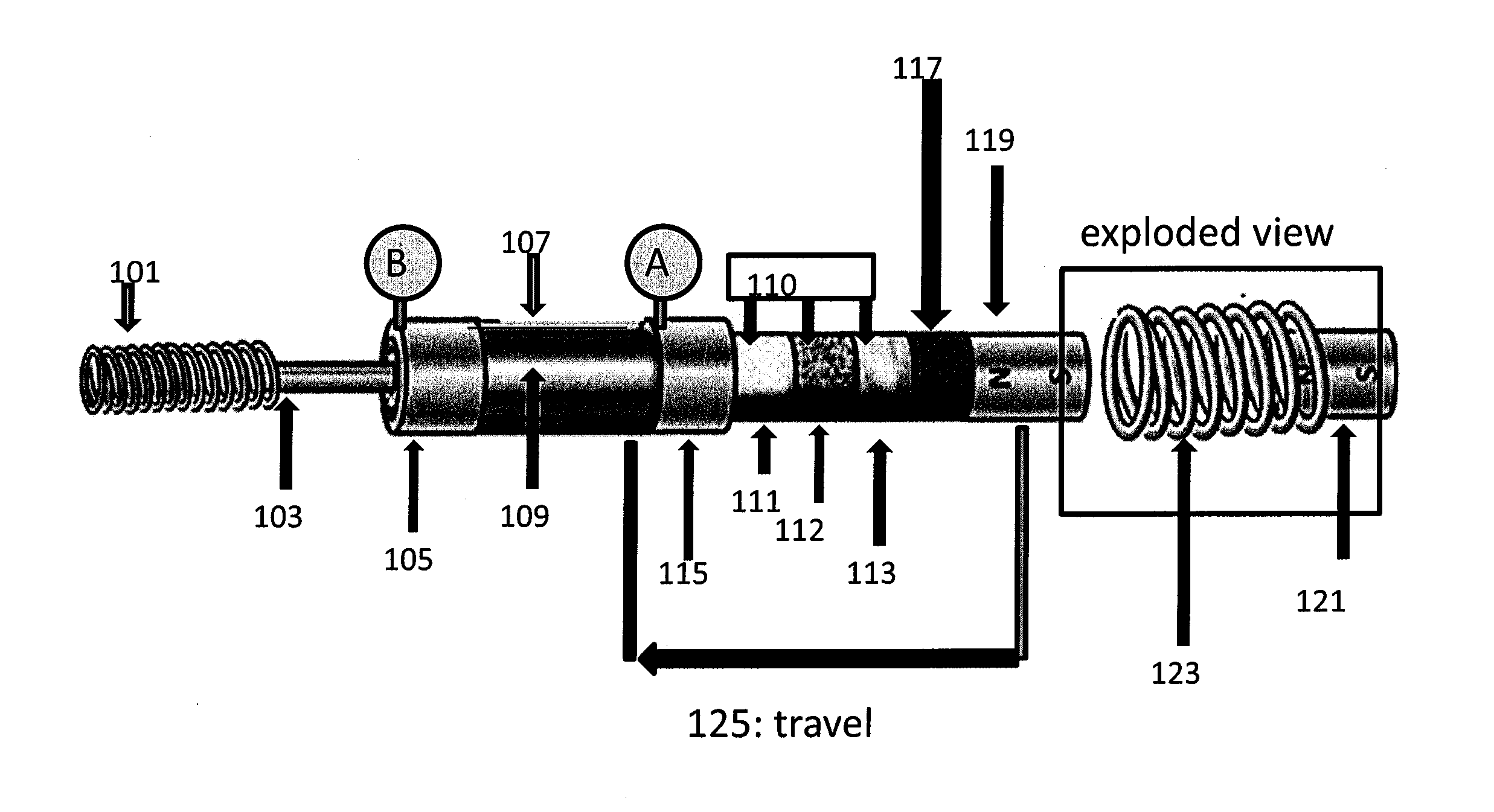
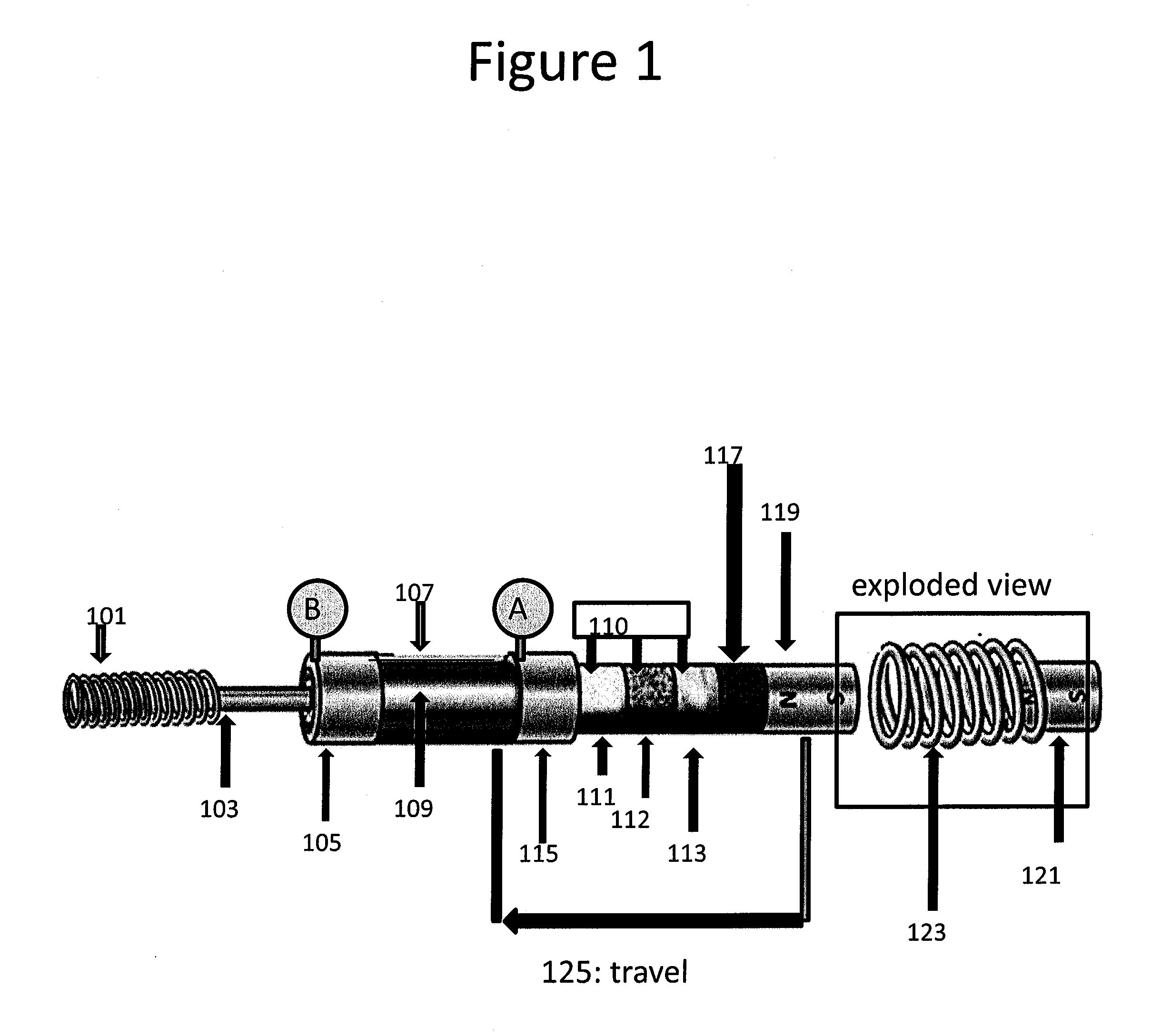
[0027]In Case (2) above of a commutating shuttle, the resistors remain stationary, and the commutating shuttle delivers the power to different stator electrodes as it moves, which connect the power flow through a sequence of stationary resistors in such a way that resistance increases repeatedly during opening of the Commutating Circuit Breaker. In this case, at least one of the stator electrodes on the commutating shuttle must be a discrete stator electrode which is bounded by insulation. Insofar as the mass of resistors required to open a circuit depends on the total energy that must be absorbed, and can be in the hundreds of kilograms for a Commutating Circuit Breaker designed for a high power, high voltage line, it is preferable in high power applications not to accelerate the resistors as in Case (1), but to rely instead on a commutating shuttle as in Case (2) to commutate the power over a series of stationary resistors. The commutating shuttle can both weigh less and be composed of stronger, stiffer materials than the variable resistance shuttle of Case (1). The lower mass of a commutating shuttle compared to a variable resistance shuttle implies less momentum needs to be transferred to accelerate the shuttle, which minimizes the jolt due to acceleration of the shuttle, and also reduces shock, vibration, and fatigue for the structure that holds the Commutating Circuit Breaker.
[0028]A commutating variable resistance shuttle as in Case (3) above is useful for snubbing arc currents that might otherwise arise as the trailing edge of a commutating stator electrode leaves its electrical connection to a particular moving shuttle electrode. Making the last half of a stator electrode and / or a shuttle electrode lower in conductivity compared to the first half can suppress arcing while still preserving a low resistance path through the first half of the stator electrode or shuttle electrode to conduct electricity efficiently when the circuit is closed. Making the trailing edge of a shuttle electrode much more resistive than a metal may imply either placing a portion of the resistance insertion of a Commutating Circuit Breaker on board the shuttle in the trailing portion of the shuttle electrodes, or within the trailing portion of the stator electrodes, or both. This approach helps to suppress arcing as a stator electrode loses contact with a particular shuttle electrode; having the trailing edge of the shuttle electrode and / or stator electrode much less conductive than the main body of the shuttle electrode or stator electrode suppresses formation of an arc as the shuttle electrode and stator electrode separate, by commutating the current to the next parallel connection prior to separation of the electrodes.
[0031]MVDC allows efficient power distribution in industrial facilities (especially factories and processing plants that use a lot of variable speed motors); on board ships; and at mine sites and other isolated off-grid sites. The provision of DC power to many different variable speed motor drives saves both capital and energy costs compared to the normal mode of operation in which each motor controller for a variable speed drive must first produce DC power from AC power within the drive, then either drive a DC motor or convert to AC at a controlled frequency to drive the variable speed motor. Variable speed drives are less expensive and more efficient if they are powered by MVDC, which has previously been impossible due to the lack of fast, efficient, economical MVDC Commutating Circuit Breakers.
[0033]The Commutating Circuit Breaker is a breakthrough in terms of capital cost and operating characteristics (long life, low switching transients) that will enable DC grids all the way from the modest voltage relevant for data centers (˜400 volts) to MVDC for microgrids, ships, and factories & processing plants, to HVDC for long distance power sharing.

Problems solved by technology

In the prior art, switching over multiple different paths through the circuit breaker after the initial commutation is accomplished by separate switches, with the added burden to guarantee exact synchronization of the switching events.
One can go to higher voltage in principle with arc chute breakers, but the needed physical separation of the electrodes increases linearly with voltage in such devices, and so they become impractically large at voltage higher than 3.5 kV.
Because of the long time that it takes to extinguish the arc, a lot of energy (far more than just the stored magnetic energy in the circuit at full load) must be dissipated into the arc chutes, which get quite hot.
This switch by itself is not useful as a high power DC circuit breaker; however, it can be combined with a switched array of resistors as in U.S. Pat. No. 3,534,226 to create a DC circuit breaker.
A problem with this design is that the current has to be high enough to heat up the thermistor for the proposed mechanism of Steurer et al to work properly.

Method used


Image

  • Commutating Circuit Breaker
  • Commutating Circuit Breaker
  • Commutating Circuit Breaker

Examples


case 1

(Case 1)

I(t)=Vt / L→dI / dt=V / L  (3)

case 2

(Case 2)

I(t)=(V / R){1−exp[−t / (L / R)]}  (4)

[0222]FIG. 18 shows a plot of these two equations for the intermediate inductance case (150 microhenries) of Example 2; up to normal full load of 2 kA, the two plots are nearly the same, but they diverge significantly at higher current, longer time. Given the very low assumed value of minimum system inductance L (1.0 microhenries), in the absence of added inductance, dI / dt (change of current with time in a dead short) is six billion amps / second. In order to limit this current rise to no more than 10 kA (starting from 2 kA, normal full load), it would be necessary to insert the first resistance at 1.33 microseconds. This is simply impossible for a mechanical system; only hybrid designs such as FIG. 15 with the very fastest types of switches (IGBT transistors or cold cathode vacuum tubes) can work in less than two microseconds as is needed if system inductance is only one microhenry. Table 3 gives the time delays for a system initially carrying ...

example 1

[0225]Consider a circuit breaker of the style of FIG. 15, in which the fast switch is a cold cathode vacuum tube of the type disclosed in U.S. Pat. No. 7,916,507 to Curtis Birnbach. Such a tube would have an on-state voltage drop of about 10 volts, which implies energy loss of about 10 / 6000 or ˜0.17% of transmitted power (better than an IGBT and not needing water cooling). This kind of tube can switch in less than 0.1 microsecond, easily commutating power to the Commutating Circuit Breaker before the current inrush passes the 10 kA maximum level, even at one microhenry inductance.

[0226]In this case, the vacuum tube is doing the “heavy lifting” and if the system inductance really is only one microhenry, then there is very little inductive energy to dissipate: only 100 joules if the current is interrupted at 10 kA, so it appears that a small capacitor or varistor could be used to absorb this energy. The advantages offered by the Commutating Circuit Breaker would be negligible in this ...


PUM


Abstract

A commutating circuit breaker that progressively inserts increasing resistance into a circuit via physical motion of a shuttle that is linked into the circuit by at least one set of sliding electrical contacts on the shuttle that connect the power through the moving shuttle to a sequence of different resistive paths with increasing resistance; the motion of the shuttle can be either linear or rotary. At no point are the sliding stator electrodes separated from the matching stationary stator electrodes so as to generate a powerful arc, which minimizes damage to the sliding stator electrodes. Instead, the current is commutated from one resistive path to the next with small enough changes in resistance at each step that arcing is suppressed. The variable resistance can either be within the moving shuttle, or the shuttle can comprise a commutating shuttle that moves the current over a series of stationary resistors.

Description

CROSS REFERENCE TO RELATED APPLICATIONS[0001]This application claims priority to the following U.S. Provisional Applications, the disclosures of which are incorporated herein by reference:[0002]1. Application Number 61439871; Filing Date 5 Feb. 2011[0003]2. Application Number 61541301; Filing Date 30 Sep. 2011FIELD[0004]This invention relates to electrical circuit breakers.BACKGROUND OF THE INVENTION[0005]In order to open any DC circuit, the inductive energy stored in the magnetic fields due to the flowing current must be absorbed; it can either be stored in capacitors or dissipated in resistors (arcs that form during opening the circuit are in this sense a special case of a resistor). Because of the rapid inrush of current in a dead short, the inductive energy can easily be much greater than just the inductive energy stored in the system at full normal load; if the current goes to double the normal full load amps before being controlled, the inductive energy would be up to four tim...

Claims


Application Information

Patent Timeline
Patent Type & Authority Applications(United States)
IPC IPC(8): H01H33/16
CPCH01H33/16H01H33/32H01H33/596H01H33/38H01H33/34H01H33/161H01H33/22H01H2201/004
Inventor FAULKNER, ROGER W.
Owner INNOLITH ASSESTS AG
Learn More