
Curable epoxy resin composition

Inactive Publication Date: 2012-08-09
ABB RES LTD
View PDF5 Cites 26 Cited by
  • Summary
  • Abstract
  • Description
  • Claims
  • Application Information

AI Technical Summary

Benefits of technology

[0016]An exemplary composition can address a technical problem of producing a curable epoxy resin composition which upon curing yields a cured epoxy resin composition useful as an encapsulant in medium to high voltage electrical equipment that combines, at comparatively low cost, excellent accuracy class performance with a cracking resistance at temperatures as low as about minus 70° C. (−70° C.), and which can be used as an encapsulant without any padding. In addition, these properties are obtained with no loss to the Automated Pressure Gelation (APG) processability or to the vacuum casting process of the curable epoxy resin composition, whereby the cured epoxy resin composition substantially retains the mechanical, thermal ageing and dielectric properties as obtained in other epoxy resin compositions. By using an exemplary composition, the amount of processing equipment required is reduced. The direct addition of all the components translates into no change to the existing manufacturing setup. A reduction in the amount of catalyst further reduces the cost per epoxy casting.

Problems solved by technology

Encapsulating insulation materials in electrical applications, such as epoxy insulations, surrounding metal coils in electrical instrument transformers are prone to cracking at low temperatures, for example, below 0° C. This is mainly due to the difference in the Coefficient of Thermal Expansion (CTE) of the epoxy insulation system which generally is comparatively high and the Coefficient of Thermal Expansion (CTE) of the metal coil which is comparatively low.
Epoxy resins being used as encapsulant for electrical equipment do not fulfill the low temperature cracking requirements.
A high glass transition temperature (Tg) of the epoxy resin composition that on curing is much higher than room temperature (RT<Tg), generally causes a high curing shrinkage of the epoxy resin composition in its glassy state, which subsequently causes internal stress of the cured composition.
The internal stress then results in bending of the encapsulated metal insert, such as a magnetic core in an instrument transformer, and hence making the electrical commodity go out of accuracy class.
However, the major shortcoming of this technique is the difficulty in exfoliating the nanoclay particles for obtaining a sufficiently increased surface area contact and maximum CTE reduction.
Inclusion of such components into the epoxy resin composition is technically difficult, generally changes the physical properties of the epoxy resin composition and is cost and processing intensive.
However, such manual padding requiring additional production steps is time consuming, and considerably raises the production costs of the transformer.
These documents, however, do not disclose, for example, improving the cracking resistance and at the same time also the accuracy class standard of sufficient flexibility for electrical encapsulating materials based on cured epoxy resin compositions as may be desirable or required when these compositions are used as an encapsulant for encapsulating insulation materials in electrical applications surrounding magnetic cores such as in medium to high voltage electrical equipment, for example in electrical instrument or distribution transformers.

Method used


Image

  • Curable epoxy resin composition
  • Curable epoxy resin composition
  • Curable epoxy resin composition

Examples


examples 1a to 1d

[0060]The epoxy resin, the hardener components, as well as the further additives as listed in Table 1 were intensively mixed in a vessel under application of vacuum as given for the Examples 1A, 1B, 1C and 1D. Analogously a comparative Example was prepared, named “Reference”, being a comparative composition as given in Table 1.

TABLE 1Refer-ExampleExampleExampleExampleComponentsence1A1B1C1DCY 228-11001001009090(Resin)DER 732P1010(Resin)HY 9188570656565(Hardener)PEA D40015101010(Hardener)PEA D2000121212(Hardener)DY0452020202020(Flexibilizer)DY 0620.50.150.150.150.15(Catalyst)TD 202 (Color)1.51.51.51.51.5W12 (Filler)385384391391448BYK W9010222(Processingaid)CY 228-1 (Resin): DGEBA with an epoxy equivalent of 5.1 Eq / kgDER 732P (Resin): long chain polypropylene glycol diglycidyl ether, average molecular weight: 600HY 918 (Hardener): MTHPA; molecular weight (mw): 166.PEA D400 (Hardener): poly(ethyleneoxy)amine; mw: 400PEA D2000 (Hardener): poly(ethyleneoxy)amine; mw: 2000DY045 (Flexibiliz...

example 2

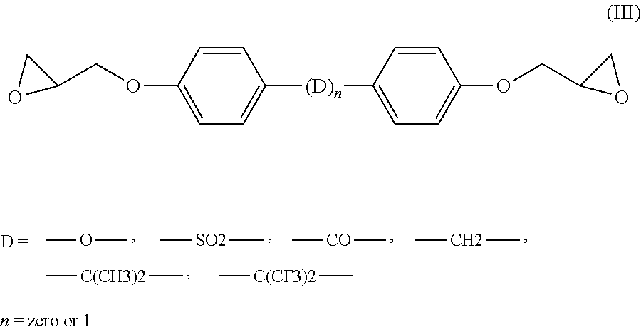
[0061]Analogous results are obtained when the epoxy resin CY 228-1 as used in the compositions of Table 1 is replaced by a resin of formula (III) wherein D=[—CH2—].

example 3

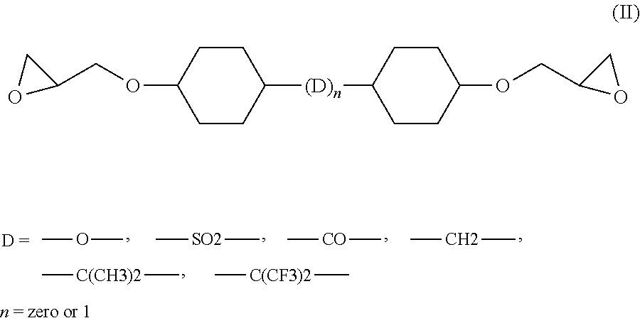
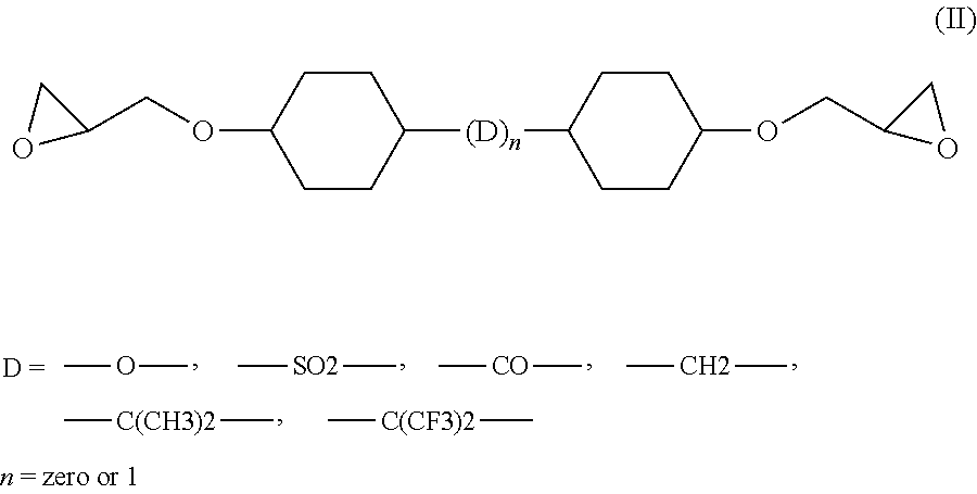
[0062]Analogous results are obtained when the epoxy resin CY 228-1 as used in the compositions of Table 1 is replaced by an aliphatic resin of formula (II) wherein D=[—C(CH3)—] or D=[—CH2—], such as Araldite® CY 184 (Huntsman Advanced Materials Ltd.), a cycloaliphatic diglycidylester epoxy resin compound having an epoxy content of 5.80-6.10 (equiv / kg) or Araldite® CY 5622 (Huntsman Advanced Materials Ltd.), a modified diglycidylester epoxy resin compound having an epoxy content of 5.80-6.10 (equiv / kg).


PUM

PropertyMeasurementUnit
Temperatureaaaaaaaaaa

Abstract

A curable epoxy resin composition including at least an epoxy resin component and a hardener component, and optionally further additives, wherein: (a) the epoxy resin component is an epoxy resin compound or a mixture of such compounds; (b) the hardener component includes (b1) an aliphatic and cycloaliphatic or aromatic polycarbonic acid anhydride; and (b2) a polyether-amine of the general formula (I), H2N—(CnH2n—O)m—CnH2n—NH2, wherein n is an integer from 2 to 8; and m is from about 3 to about 100; (c) the polycarbonic acid anhydride [component (b1)] is present in the curable epoxy resin composition in a concentration of 0.60 Mol to 0.93 Mol; and (d) the polyether-amine of the general formula (I) [component (b2)] is present in the curable epoxy resin composition in a concentration of about 0.02 Mol to about 0.1 Mol.

Description

RELATED APPLICATION(S)[0001]This application claims priority as a continuation application under 35 U.S.C. §120 to PCT / EP2009 / 061038 filed as an International Application on Aug. 27, 2009 designating the U.S., the entire content of which is hereby incorporated by reference in its entirety.FIELD[0002]The present disclosure relates to a curable epoxy resin composition comprising at least an epoxy resin component and at least a hardener component, said hardener component being a combination of a phthalic acid anhydride and a defined polyether-amine and wherein the phthalic acid anhydride and the polyether-amine are present in defined ratios. The resulting cured epoxy resin composition has a cracking resistance at temperatures as low as about minus 70° C. (−70° C.) combined with an excellent accuracy class performance and can be used as an encapsulating material for medium to high voltage electrical equipment, for example, for applications where the material is subjected to thermal shoc...

Claims


Application Information

Patent Timeline
IPC IPC(8): H01B3/40C08K9/00C08L63/00
CPCC08G59/4284C08L63/00C08G59/58H01B3/40
Inventor SINGH, BANDEEPSCHAAL, STEPHANEKORNMANN, XAVIERPURI, PRATEEK
Owner ABB RES LTD
Learn More