Method and device for energy harvesting

a technology of energy harvesting and energy storage, applied in the direction of piezoelectric/electrostrictive transducers, generators/motors, transportation and packaging, etc., can solve the problems of increasing the operation time of these systems, increasing the power level required by applications, and unable to fully utilize wireless communication capabilities, etc., to maximize the harvesting energy, low power applications, and small size

Active Publication Date: 2012-08-16
MURATA MFG CO LTD
View PDF5 Cites 10 Cited by
  • Summary
  • Abstract
  • Description
  • Claims
  • Application Information

AI Technical Summary

Benefits of technology

[0010]An object of the invention is to overcome or at least alleviate drawbacks related to the known prior art solutions, such as to maximize harvested energy without limiting a harvester mechanical resonance frequency for a certain frequencies. In addition the invention aims to allow an easy manufacturing process of the energy harvester.
[0014]According to an embodiment the piezoelectric element is used also to generate electrical power to the power output from vibration and / or strain in addition to generating the bias voltage. This enhances the efficiency of the harvesting device since the output power is generated both the capacitive and piezoelectric features.
[0017]In addition according to an embodiment of the invention the capacitor plates are moved in relation with each other into a semi-contact mode. In other words the plates are as close to each other than possible when the gap is minimized and separated essentially only by the thin dielectric film. The dielectric film or bumps act as a mechanical stopper, and thereby protects the capacitor plates against wear and short circuits, and the harvester structure from breaking under vibration exceeding the limits of the intended use. A high dielectric constant of the film maximizes the capacitance difference at open and closed positions with modest spring displacement amplitudes. The dielectric film may comprise for example silicon oxide, aluminium oxide or DLC (diamond like carbon). The film thickness is according to an embodiment advantageously 25 nm at maximum. It is preferable that the spring and mass are designed such that the electrodes touch each other via the dielectric film at a certain alignment / position of the harvester, possibly in a stationary state of the harvester, and at least in its normal use. For example, if the harvester is rotating in its normal use, the harvester is arranged to reach such a position during every rotation. Thus the electrodes touch via the film on every turn, and a high / maximal capacitance is achieved at this loading period of the harvester. At the work period, when the electrodes recede apart each other, high / maximum energy is thus obtained. In vibrating use, for example, the loading period and the work period are repeated in a corresponding manner during the vibration cycle, whereby the electrodes touch each other at the loading period of the vibration. During the loading period, the bias voltage is preferably applied to the electrodes.
[0020]The invention offers clear advantages over the known prior art solutions, such as maximized harvested energy due to e.g. the semi-contact mode and maximizing the capacitance change by using thin dielectric film. In addition no additional battery is needed for enabling the functioning of the capacitor harvester, since the piezoelectric film is used to generate the bias voltage for the capacitor harvester. Furthermore the harvester according to the invention is independent of the component's mechanical resonance frequency, since the gap between the capacitor plates will open and close at every strike. Moreover the harvester structure is durable due to in-built stoppers protecting the moving parts at large accelerations. The thin film between the plates also protects the capacitor plates against wear and short circuits, as well as also in its part the harvester structure from breaking under vibration exceeding the limits of the intended use. The harvester structure is also simple, easy and cost effective to manufacture, because it can be processed with existing methods and tools, such as SOI (Silicon on insulator technology) or MEMS (microelectromechanical systems) technology.
[0021]In addition the energy harvester of the invention can be integrated with different kinds of electronic devices. Because the harvester of the invention replaces the conventional batteries and power sources, the harvester also removes the need for changing the batteries and / or loading the power sources. Especially the harvester is ideally for powering wireless applications. In addition the use of e.g. MEMS offers a compact and cost effective solution for manufacturing the harvester component enabling a small scale production at the same time.

Problems solved by technology

The wireless communication capabilities cannot be fully utilized if energy is supplied by wires, or if there is a battery with limited operation time, bulky size, and large weight.
There are already battery operated devices on the market, but harvesters would increase the operation time of these systems.
However, the power levels required by the applications are constantly decreasing while the harvested power levels are increasing.
However, some disadvantages relate to the known prior art solutions.
However, the devices with plurality of members become quite complex to manufacture.
Also many of the known harvesters are vulnerable to vibration exceeding the limits of the intended use.

Method used


Image

  • Method and device for energy harvesting
  • Method and device for energy harvesting
  • Method and device for energy harvesting

Examples


Embodiment Construction

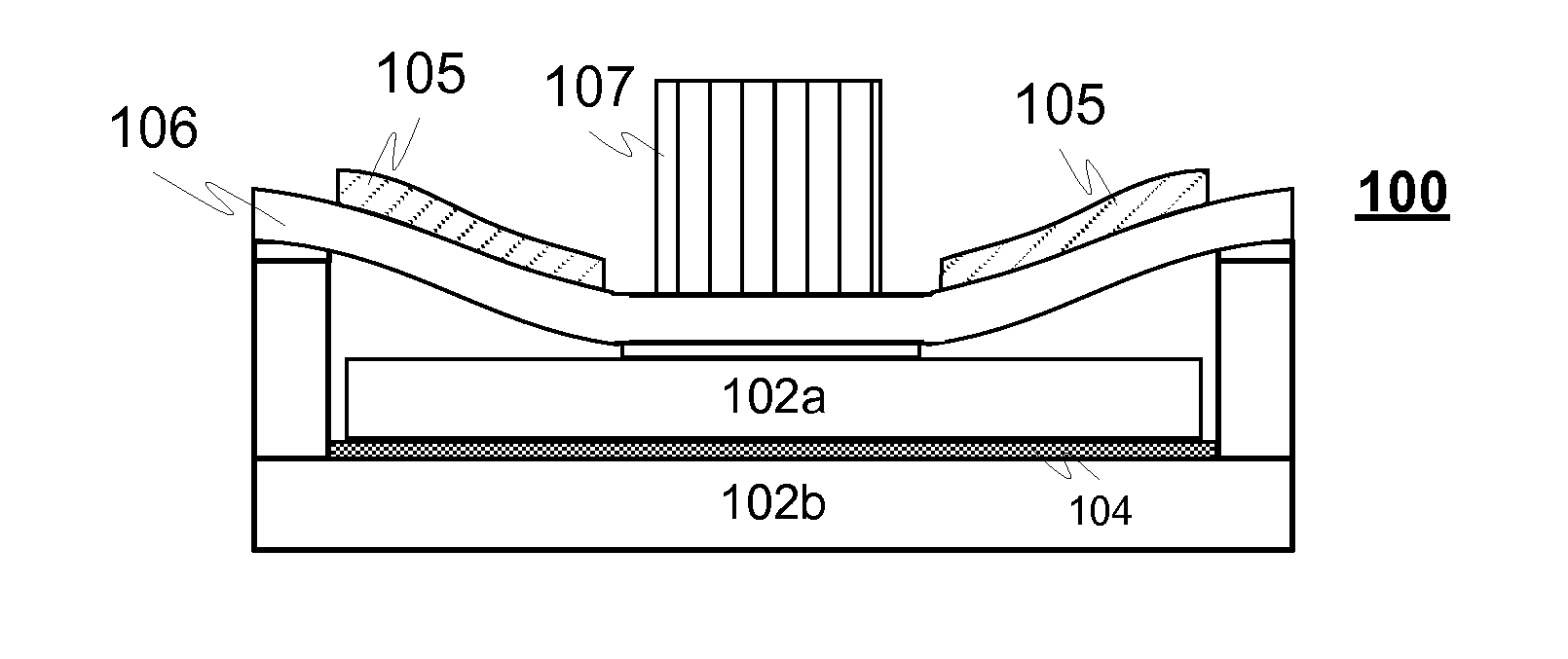
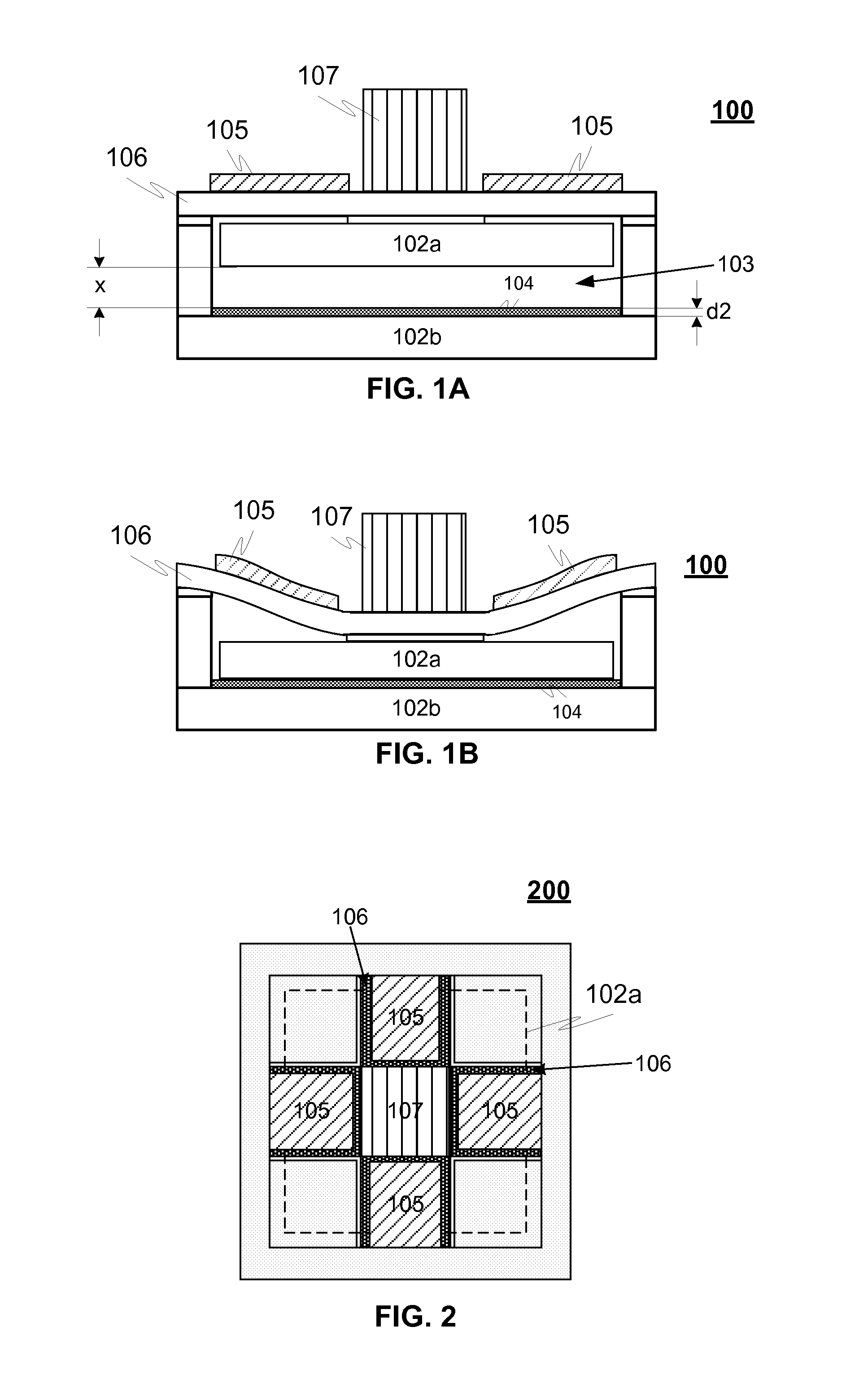
[0027]FIGS. 1A-B illustrate an exemplary device 100 for energy harvesting from vibration, strain, turn and / or strike according to an advantageous embodiment of the invention, wherein in FIGS. 1A-B shows also the principle of operation of the device 100, where the device is in an open position and in FIG. 1B in a closed position.

[0028]The device 100 advantageously comprises a capacitor harvesting module comprising two capacitor plates 102a, 102b arranged essentially parallel with each other so that at least one of the plates 102a is adapted to move due to vibration, strain, turns and / or strike in an essentially perpendicular direction to the other capacitor plate 102b and thereby forming a variable gap 103 between the plates. Due to the changing distance the capacitance between the plates 102a, 102b is also changed and thereby also electrical power is generated to a power output. For example when the device 100 is utilised in a wheel, the capacitor is closed and opened at every strik...


PUM

PropertyMeasurementUnit
thicknessaaaaaaaaaa
poweraaaaaaaaaa
thickness d2aaaaaaaaaa

Abstract

A device (100) harvests energy from vibration and / or strain and utilises both capacitive (102a, 102b) and piezo-electric elements (105). The principle of operation is out-of-plane capacitive harvester, where the bias voltage for the capacitive element is generated with a piezoelectric element (105). The device utilizes a thin dielectric film (104) between the capacitor plates (102a, 102b) maximizing the harvested energy and enabling the harvester operation in semi-contact mode so that short circuits are prevented. For example when utilised in a wheel or the like, the capacitor is closed and opened at every strike or every turn of a wheel being thus independent of the harvester's mechanical resonance frequency.

Description

TECHNICAL FIELD OF THE INVENTION[0001]The invention relates to a device and method for energy harvesting from vibration, strain, turn and / or strike.BACKGROUND OF THE INVENTION[0002]Over the past few decades, the need of powering e.g. wireless sensors has initiated the research activity on energy harvesting from the environment. The wireless communication capabilities cannot be fully utilized if energy is supplied by wires, or if there is a battery with limited operation time, bulky size, and large weight.[0003]The energy harvesting mechanism depends on the environment and the application. Various energy sources have been proposed: light, heat (thermal gradient), strain, vibrations, electromagnetic field, kinetics, air flow, pressure variations, and radioactive materials, as well as also vibration.[0004]One of most studied application for energy harvesting is e.g. car tyre pressure monitoring systems TPMS. There are already battery operated devices on the market, but harvesters would...

Claims


Application Information

Patent Timeline
Patent Type & Authority Applications(United States)
IPC IPC(8): H02N1/08H01L41/22H02N2/18
CPCB60C23/0411Y10T29/42H02N2/186H10N30/304B81B3/0021H02N1/08H10N30/30B81B3/00B60C23/04
Inventor KARKKAINEN, ANNA-MAIJAKYYNARAINEN, JUKKAROSCHIER, LEIFKUISMA, HEIKKI
Owner MURATA MFG CO LTD
Why Eureka
Try Eureka