Variable gain amplifier

a gain amplifier and variable gain technology, applied in amplifiers with impedence circuits, amplifiers with semiconductor devices/discharge tubes, amplifiers, etc., can solve the problems of difficult adaptation of attenuators to amplifier impedances, generation of intermodulation noise, etc., to improve the noise figure and linearity of a vga

Active Publication Date: 2012-08-16
NXP BV
View PDF4 Cites 14 Cited by
  • Summary
  • Abstract
  • Description
  • Claims
  • Application Information

AI Technical Summary

Benefits of technology

[0009]Hence, it is a need, to improve the noise figure and the linearity of a VGA.

Problems solved by technology

However, this known architecture generates intermodulation noise, the attenuator being hard to adapt to the amplifiers impedances in whole frequency range.

Method used


Image

  • Variable gain amplifier
  • Variable gain amplifier
  • Variable gain amplifier

Examples


Embodiment Construction

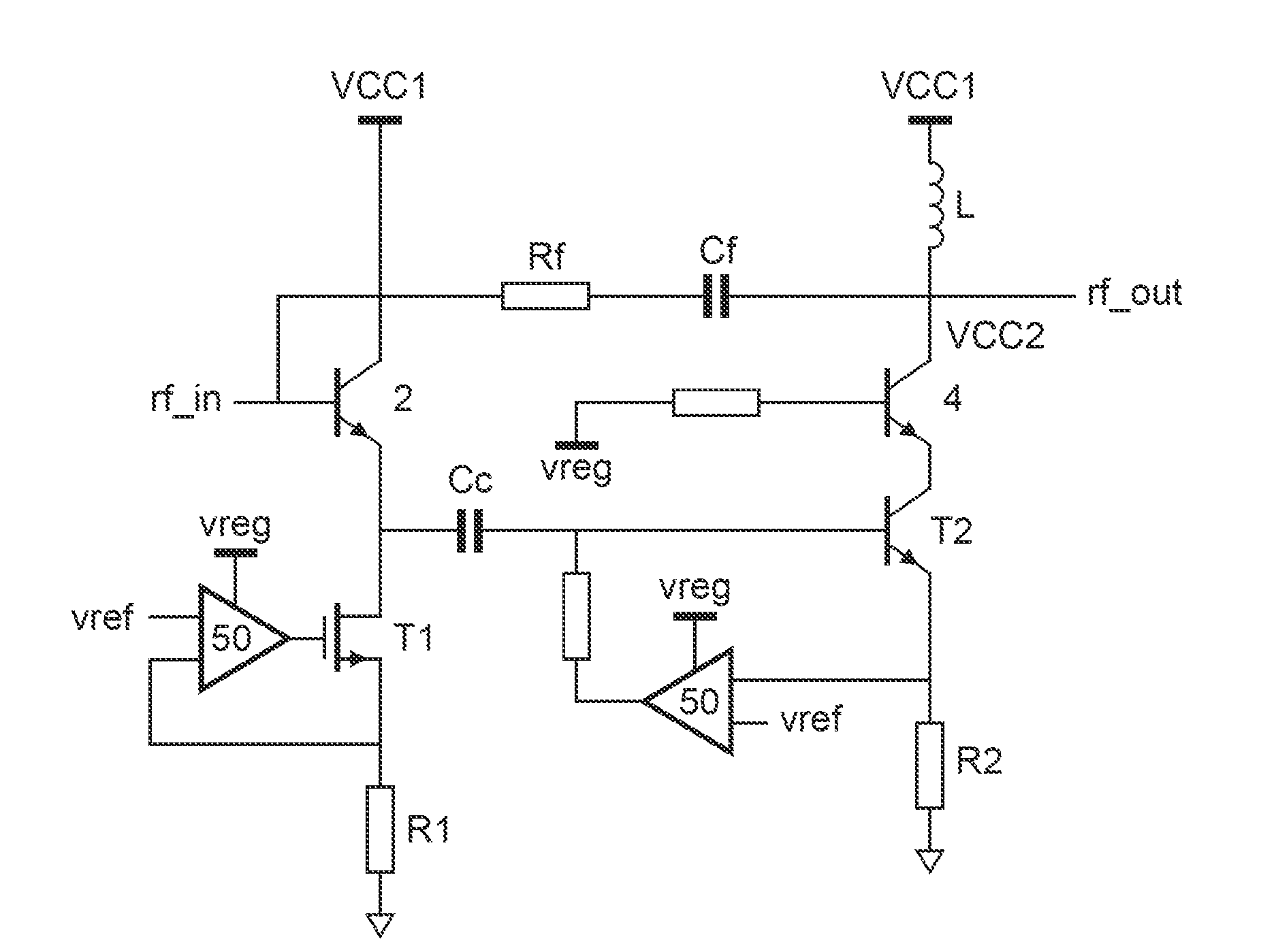
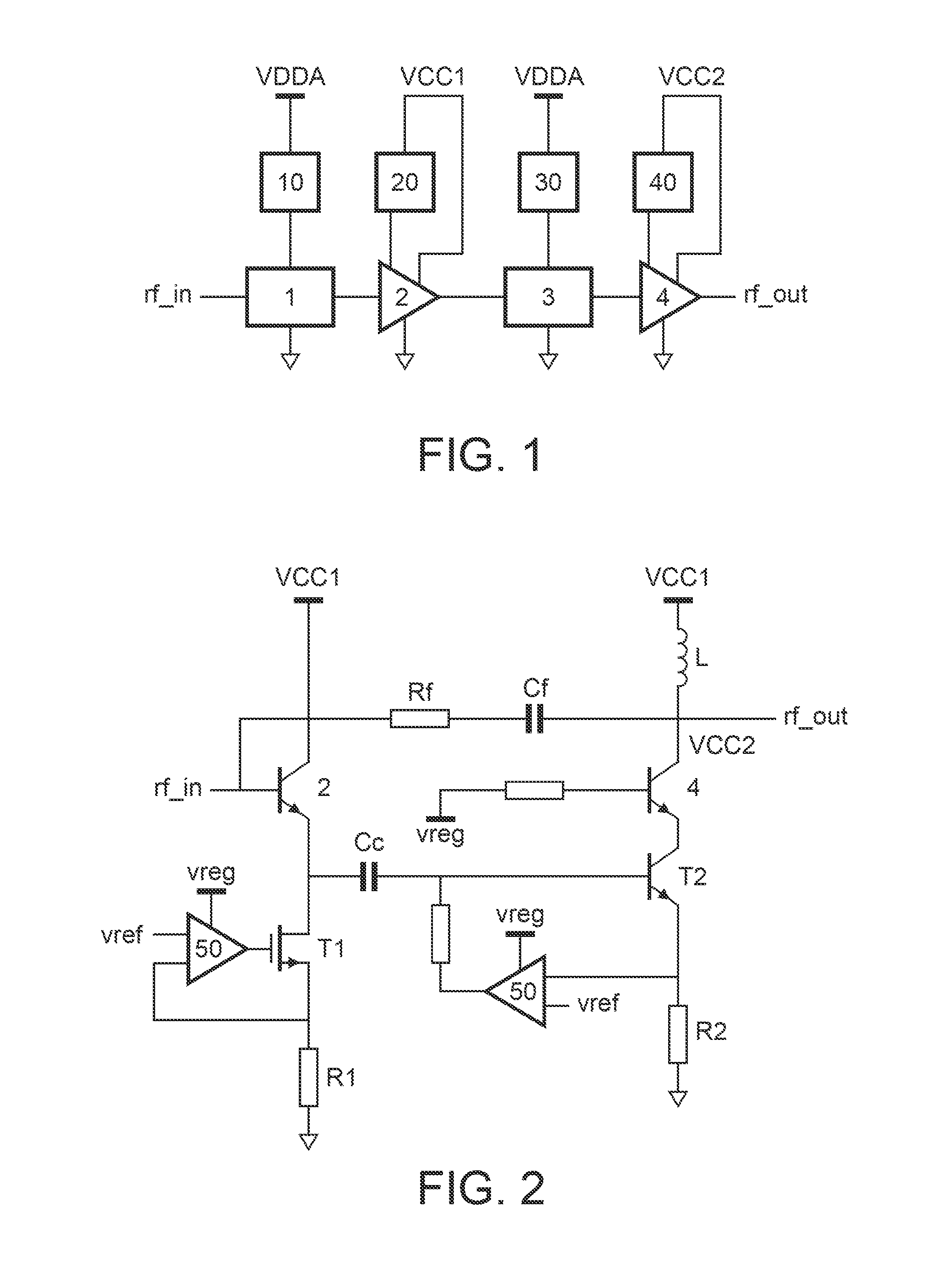
[0029]FIG. 1 depicts a variable gain amplifier, according to the invention. The variable gain amplifier comprises a first attenuator 1 for receiving an input signal rf_in and for transmitting a first attenuated input signal to a first amplifier 2 for amplifying the first attenuated input signal and for generating a first amplified signal to a second attenuator 3 for attenuating the first amplified signal and for transmitting a second attenuated signal to a second amplifier 4 for amplifying the second attenuated signal and for generating an output signal rf_out. The first attenuator 1 is supplied from a first supply voltage source 10. The second attenuator 3 is supplied from a second supply voltage source 30. The first amplifier 2 is supplied from a third supply voltage source 20, and the second amplifier 4 is supplied from a fourth supply voltage source 40. Each of the voltage sources is provided by respective separate voltage regulators. The advantage of separating the supply volta...


PUM


Abstract

The invention relates to a variable gain amplifier comprising a first attenuator (1) for receiving an input signal (rf_in) and for transmitting a first attenuated input signal to a first amplifier (2) for amplifying the first attenuated input signal and for generating a first amplified signal to a second attenuator (3) for attenuating the first amplified signal and for transmitting a second attenuated signal to a second amplifier (4) for amplifying the second attenuated signal and for generating an output signal (rf_out). The first attenuator (1) is supplied from a first supply voltage source (10). The second attenuator (3) is supplied from a second supply voltage source (30). The first amplifier (2) is supplied from a third supply voltage source (20), and the second amplifier (4) is supplied from a fourth supply voltage source (40).

Description

FIELD OF THE INVENTION[0001]The invention relates to variable gain amplifier.BACKGROUND OF THE INVENTION[0002]Variable gain amplifiers (VGAs) are used inter alia in receiving and transmitting paths of basestations for conditioning the amplitude of a Radio Frequency (RF) signal for various gain variations as signal level at the antenna or gain spread of the electrical components.[0003]In the RF spectrum ranging from 0.7 GHz to 3.8 GHz it is very necessary to keep an almost constant and linear amplification with a signal to noise ratio as large as possible. These tasks are not trivial to achieve when such a large frequency range is involved.[0004]Known prior art VGA amplifiers comprise a series connection of a small signal amplifier followed by an attenuator and further followed by a large signal amplifier. However, this known architecture generates intermodulation noise, the attenuator being hard to adapt to the amplifiers impedances in whole frequency range. An important parameter o...

Claims


Application Information

Patent Timeline
Patent Type & Authority Applications(United States)
IPC IPC(8): H03G3/00H03G3/20
CPCH03F1/22H03F3/19H03F3/50H03F2200/144H03G1/0088H03F2200/405H03F2200/411H03F2203/5018H03F2200/211
Inventor HOOGZAAD, GIAN
Owner NXP BV
Why Eureka
Try Eureka