Heat exchanger device with heat-radiative coating

a heat exchanger and coating technology, applied in indirect heat exchangers, lighting and heating apparatus, furnaces, etc., can solve the problems of not having, previously proposed, to improve the heat storage capability and work efficiency of heat retainers, and achieve high efficiency and energy saving. , the effect of facilitating heat exchang

Inactive Publication Date: 2012-08-16
ZHOU HUIMIN
View PDF25 Cites 7 Cited by
  • Summary
  • Abstract
  • Description
  • Claims
  • Application Information

AI Technical Summary

Benefits of technology

[0007]To overcome the deficiencies of prior art, it is one objective of the invention to provide a highly-efficient and energy-saving heat exchanger with a coating layer on a part of or on the entire surface of the heat retainer for facilitating heat exchange.

Problems solved by technology

However, a heat exchanger employing a coating layer made of high radiative material has not heretofore been proposed to improve the heat storage capability and working efficiency of the heat retainer.

Method used


Image

  • Heat exchanger device with heat-radiative coating
  • Heat exchanger device with heat-radiative coating
  • Heat exchanger device with heat-radiative coating

Examples


example 1

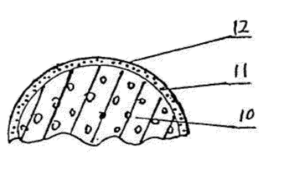
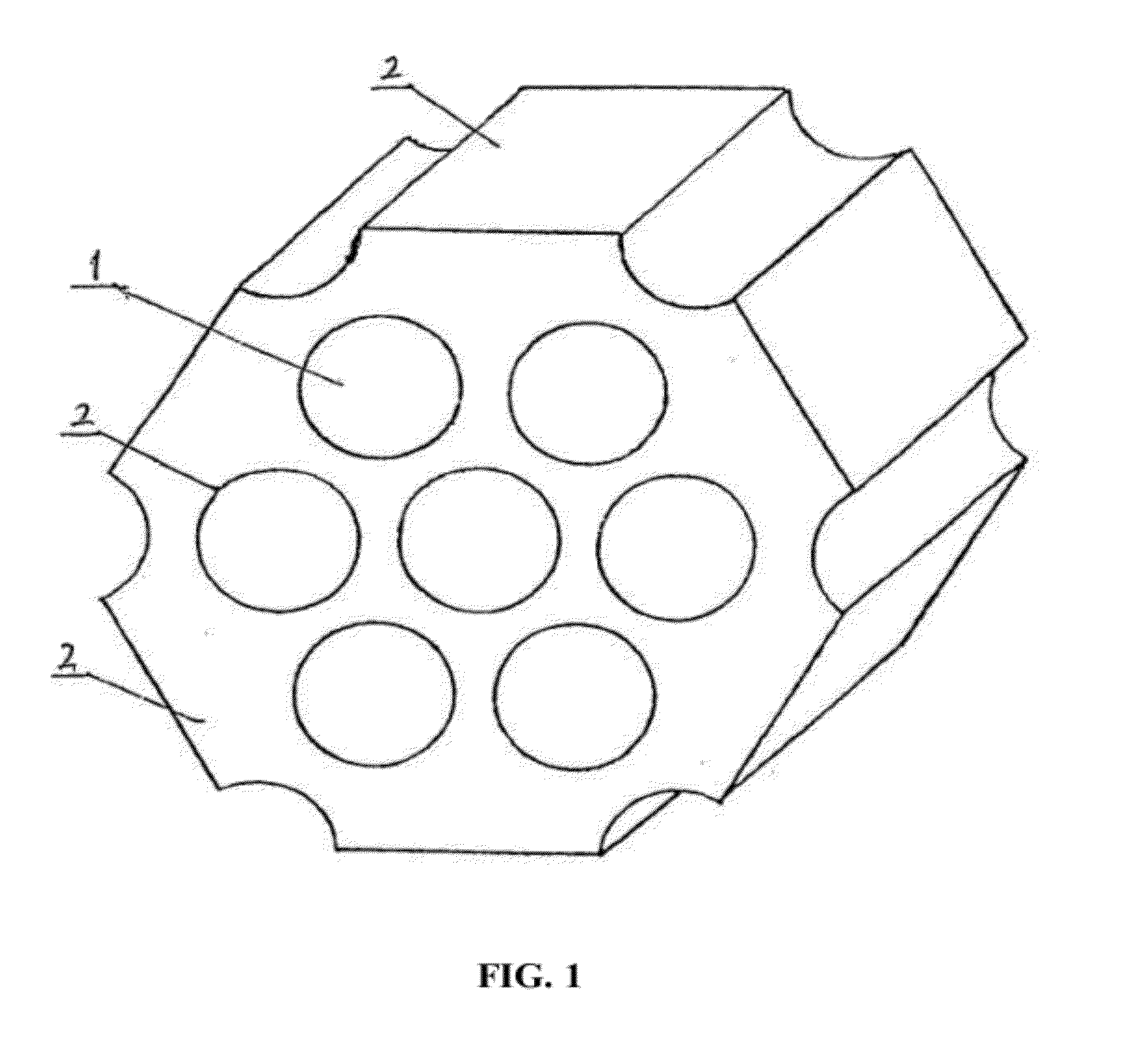
[0110]As shown in FIG. 1, a heat retainer used for a hot blast stove of a blast furnace is a checker brick. The checker brick (heat retainer) has a plurality of circular inner holes 1, and all surfaces (comprising those of the inner holes) of the check brick (heat retainer) are coated with a coating layer of a high radiative material 2 whose thickness is 0.02 mm. A substrate of the heat retainer is a refractory material, and the high radiative material coating layer 2 is a high radiative material whose emissivity in the far-infrared region is greater than that of a substrate material of the heat retainer.

[0111]The high radiative material coating layer 2 comprises by weight: 110 parts of Cr2O3, 80 parts of clays, 90 parts of montmorillonites, 300 parts of brown corundum, 100 parts of silicon carbides, 400 parts of PA80 adhesive and 100 parts of water. These components are hyperfinely processed, i.e., the mixture is grinded to particles with micro / nano-meter sizes by using superfine p...

example 2

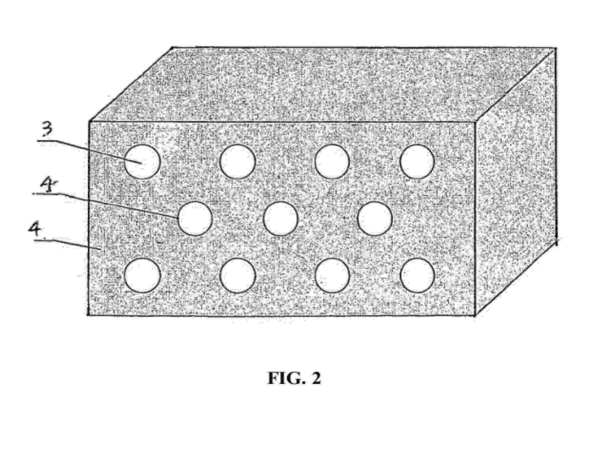
[0112]As described in example 1, except that differences are as follows: the cross section of the honeycomb-shaped heat retainer is rectangular; and the high radiative material coating layer is disposed within a plurality of circular inner holes 3 (as shown in FIG. 2).

example 3

[0113]As shown in FIG. 3, the heat retainer for a heat exchange is fin-shaped. A plurality of rectangular inner holes 5 are disposed in the heat retainer, and all surfaces (comprising surfaces of the inner holes) of the heat retainer for the heat exchanger are paste-coated with a high radiative material coating layer 6 whose thickness is 0.03 mm. A substrate of the heat retainer is a ceramic material, and the high radiative material coating layer 4 is a high radiative material whose emissivity in the far-infrared region is greater than that of a substrate material of the heat retainer.

[0114]The high radiative material comprises by weight: 15 parts of zirconium oxide, 8 parts of Cr2O3, 10 parts of TiO2, 2 parts of montmorillonites, 15 parts of Al2O3, 10 parts of carborundums, 30 parts of PA80 adhesives, and 10 parts of water. Compared with existent heat exchangers, the heat efficiency of the heat exchanger according to this example is improved by over 10%.


PUM

PropertyMeasurementUnit
temperaturesaaaaaaaaaa
thicknessaaaaaaaaaa
thicknessaaaaaaaaaa

Abstract

A heat retainer for a hot blast stove of a blast furnace, the heat retainer adapted to function without decomposition at temperatures of about 1200° C., wherein: at least one surface of said heat retainer is coated with a high radiative and highly-emissive material forming said coating layer; the thickness of said coating layer is critically between 0.02 mm and 3 mm; the heat retainer absorbs energy or emits energy mainly by radiation; and energy of radiation is mainly at a wavelength of 1-5 μm.

Description

CROSS-REFERENCE TO RELATED APPLICATIONS[0001]This application is a continuation-in-part of U.S. Ser. No. 11 / 815,488 with a 371(c) date of Aug. 3, 2007, now pending, which is a National Phase Entry application under 35 U.S.C. 371 of International Patent Application No. PCT / CN2005 / 002010 with an international filing date of Nov. 25, 2005, designating the United States, now pending. This application further claims foreign priority benefits to Chinese Patent Application No. 200510043838.X, filed on Jun. 17, 2005. The contents of all of the aforementioned specifications as originally filed, and all amendment thereto, are incorporated herein by reference.BACKGROUND OF THE INVENTION[0002]1. Field of the Invention[0003]The invention relates to a heat exchanger device and more particularly to a heat storage device having a high radiative coating layer on the surface of the heat storage device, so that facilitates heat exchange.[0004]2. Description of the Related Art[0005]In industrial fields...

Claims


Application Information

Patent Timeline
Patent Type & Authority Applications(United States)
IPC IPC(8): F28F13/18C21B9/10
CPCF28D17/02F27D1/0006C21B9/06F28F13/18
Inventor ZHOU, HUIMIN
Owner ZHOU HUIMIN
Why Eureka
Try Eureka