Orthopedic implants having gradient polymer alloys

a gradient polymer and alloy technology, applied in the field of fully interpenetrating polymer networks, can solve the problems that the mechanical properties desired for certain medical applications are often outside the range, and achieve the effect of high mechanical strength and hydrophobic starting materials

Inactive Publication Date: 2012-08-16
HYALEX ORTHOPAEDICS INC
View PDF3 Cites 54 Cited by
  • Summary
  • Abstract
  • Description
  • Claims
  • Application Information

AI Technical Summary

Benefits of technology

[0011]The mechanical properties desired for certain medical applications are often outside the range of possibility of many hydrophilic starting materials. Hence, one aspect of this invention takes advantage of the high mechanical strength of hydrophobic starting materials and combines those materials w...

Problems solved by technology

The mechanical properties desired for certain medical applications are ...

Method used


Image

  • Orthopedic implants having gradient polymer alloys
  • Orthopedic implants having gradient polymer alloys
  • Orthopedic implants having gradient polymer alloys

Examples


example 1

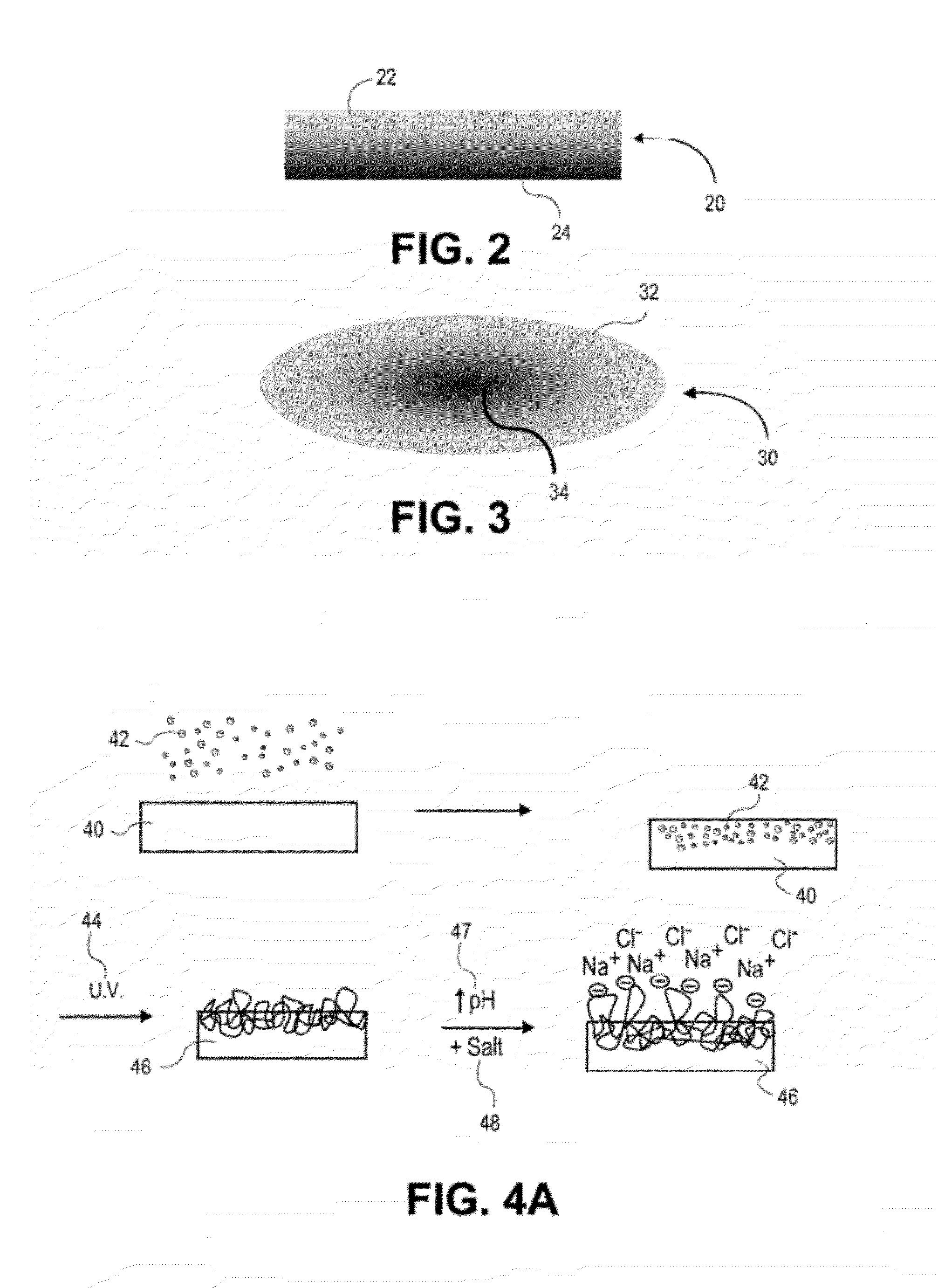
[0199]In one example, a polycarbonate urethane (Bionate 55D) was immersed in 70% acrylic acid in water containing 0.1% v / v 2-hydroxy-2-methyl propiophenone and 0.1% v / v triethylene glycol dimethacrylate with respect to the monomer overnight. The polycarbonate urethane was removed from the solution, placed between two glass slides, and exposed to UV light (2 mW / cm2) for 15 minutes. The resulting semi-IPN was removed, and washed and swollen in phosphate buffered saline. The material swelled and became lubricious within hours. In other examples, segmented polyurethane urea, as well as silicone polyether urethane and silicone polycarbonate urethanes were placed in acrylic acid solutions and polymerized and washed in the same fashion to yield a lubricious IPN.

example 2

In another example, a polyether urethane (Elasthane™ 55D) was immersed in 70% acrylic acid in water containing 0.1% v / v 2-hydroxy-2-methyl propiophenone and 0.1% v / v triethylene glycol dimethacrylate with respect to the monomer overnight. The polyether urethane was removed from the solution, placed between two glass slides, and then exposed to UV light (2 mW / cm2) for 15 minutes. The resulting semi-IPN was removed and then washed and swollen in phosphate buffered saline. The material swelled and became lubricious within hours. In other examples, polycarbonate urethane, segmented polyurethane urea, as well as silicone polyether urethane and silicone polycarbonate urethanes were placed in acrylic acid solutions and polymerized and washed in the same fashion to yield lubricious IPNs.

example 3

[0200]In another example, silicone polyether urethane and silicone polycarbonate urethanes were separately placed overnight in 100% acrylic acid solutions, to which were added 0.1% v / v 2-hydroxy-2-methyl propiophenone and 0.1% v / v triethylene glycol dimethacrylate with respect to the monomer. After polymerization and crosslinking, the semi-IPNs swelled and became lubricious. The addition of silicone (polydimethylsiloxane) in the polyurethane adds an extra level of biostability to the material as well as potentially useful surface chemistry and properties.


PUM

PropertyMeasurementUnit
Temperatureaaaaaaaaaa
Fractionaaaaaaaaaa

Abstract

Orthopedic implants having a bone interface member and a water swellable IPN or semi-IPN with a stiffness, hydration, and/or compositional gradient from one side to the other and physically attached to the bone interface member. The invention also includes an orthopedic implant system including an implant that may conform to a bone surface and a joint capsule. The invention also includes orthopedic implants with water swellable IPN or semi-IPNs including a hydrophobic thermoset or thermoplastic polymer first network and an ionic polymer second network, joint capsules, labral components, and bone interface members. The invention also includes a method of inserting an orthopedic implant having a metal portion and a flexible polymer portion into a joint, including inserting the implant in a joint in a first shape and changing the implant from a first shape to a second shape to conform to a shape of a bone.

Description

CROSS REFERENCE TO RELATED APPLICATIONS[0001]This application is a Continuation-in-Part of U.S. patent application Ser. No. 13 / 219,348 filed Aug. 26, 2011 (which claims the benefit of U.S. Provisional Application No. 61 / 377,844 filed Aug. 27, 2010 and of U.S. Provisional Application No. 61 / 383,705 filed Sep. 16, 2010), which is a Continuation-in-Part of U.S. patent application Ser. No. 12 / 499,041 filed Jul. 7, 2009, (which claims the benefit U.S. Provisional Application No. 61 / 078,741, filed Jul. 7, 2008, U.S. Provisional Application No. 61 / 079,060, filed Jul. 8, 2008, U.S. Provisional Application No. 61 / 095,273, filed Sep. 8, 2008, and U.S. Provisional Application No. 61 / 166,194, filed Apr. 2, 2009); and claims the benefit under 35 U.S.C. 119 of U.S. Provisional Patent Application No. 61 / 431,327 filed Jan. 10, 2011, U.S. Provisional Patent Application No. 61 / 454,957 filed Mar. 21, 2011, and U.S. Provisional Patent Application No. 61 / 566,567 filed Dec. 2, 2011; the disclosures of ea...

Claims


Application Information

Patent Timeline
IPC IPC(8): A61F2/32A61F2/30
CPCC08G18/4854C08G18/7671C08G18/831C08L75/16C08L33/02C08L75/04C08L75/06C08G2270/00A61F2310/00011A61F2310/00179A61F2/30A61F2/30988A61F2/3099A61F2/32A61F2/3804A61F2/3859A61F2/3872A61F2/3877A61F2/4081A61F2/4202A61F2/4225A61F2/4241A61F2/4261A61F2/442A61F2002/30998A61F2002/4205A61F2002/4238A61F2002/4256C08F220/06C08F220/14C08F236/06C08G18/44C08G18/837C08G77/38C08L2205/04
Inventor MYUNG, DAVIDJAASMA, MICHAEL J.KOURTIS, LAMPROSROBERTS, JEFFREY G.HARTDEGEN, VERNON
Owner HYALEX ORTHOPAEDICS INC
Why Eureka
Try Eureka