Semiconductor manufacturing apparatus member

Active Publication Date: 2012-08-23
NGK INSULATORS LTD
View PDF1 Cites 33 Cited by
  • Summary
  • Abstract
  • Description
  • Claims
  • Application Information

AI Technical Summary

Benefits of technology

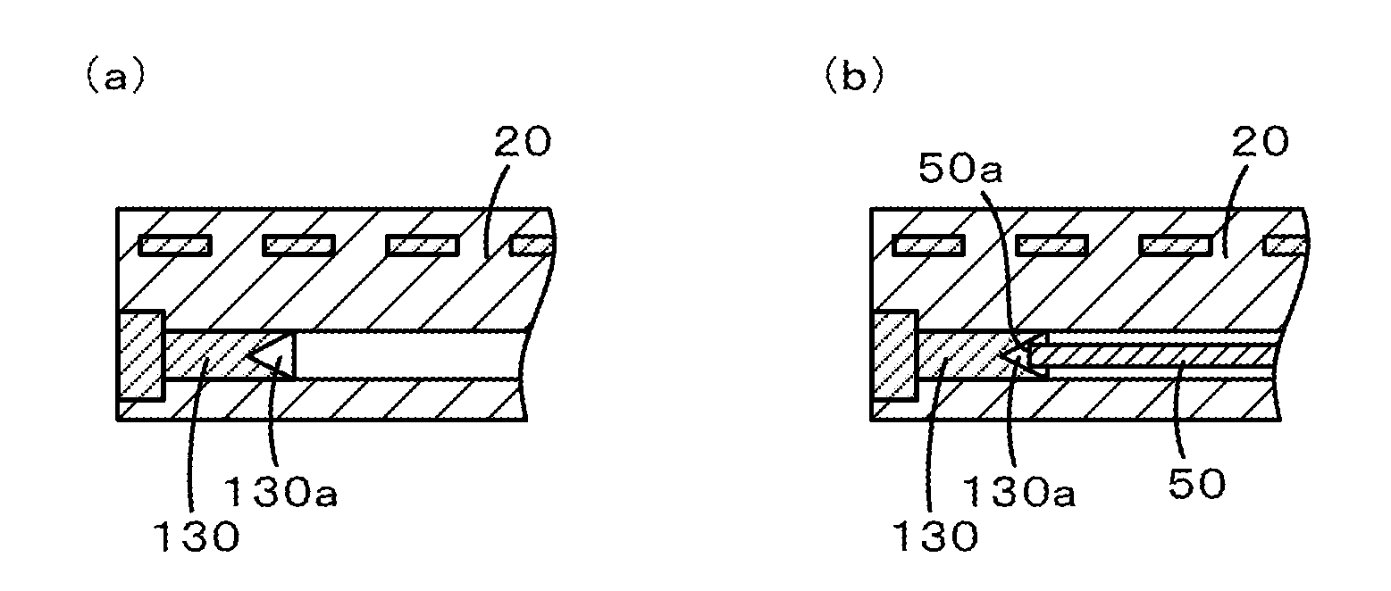
[0013]In the semiconductor manufacturing apparatus member according to the present invention, the thermocouple may be pressed by a spring so that the temperature sensing portion is in contact with the closed end. In this case, the temperature sensing portion of the thermocouple is continuously pressed against the closed end of the thermocouple conduit by the spring. Thus, the accuracy with which the temperature of an outer peripheral portion of the ceramic plate is measured is increased.

Problems solved by technology

However, when forming a hole for a thermocouple in the outer peripheral portion and disposing the thermocouple in the hole, the following problem arises.
In this case, however, it may happen that a lifter pin for raising and lowering a wafer above the wafer-placing surface cannot be set.
This is because, there may not be sufficient space for disposing the lifter pin, which is inserted into a through-ho

Method used


Image

  • Semiconductor manufacturing apparatus member
  • Semiconductor manufacturing apparatus member
  • Semiconductor manufacturing apparatus member

Examples


example 1

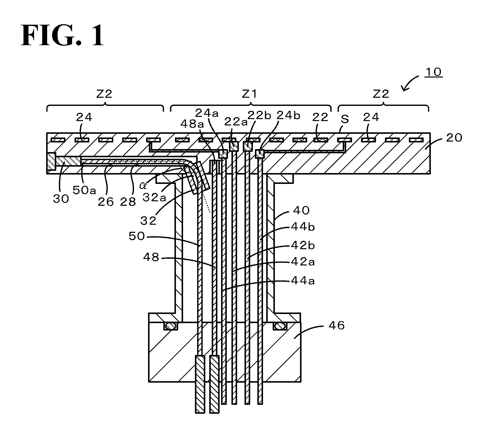
[0050]A ceramic heater having the structure illustrated in FIG. 9 was fabricated. The ceramic plate 220 used was made from AlN, had an outside diameter of φ350 mm, and was formed by solid-state bonding the upper and lower thin plates 221 and 222, each having a thickness of 10 mm, so that the bonded interface had hermeticity. The shaft 40 used had a length of 200 mm and an inside diameter of φ50 mm. The closed end of a thermocouple conduit 226 was distanced by 120 mm from the center of the ceramic plate 220. A portion of the thermocouple conduit 226 from an end near the center of the ceramic plate 220 to the tapered portion 224a had a horizontal length L2 of 100 mm, a width in the range of 2 to 3 mm, and a depth the same as the width. The tapered portion 224a had a horizontal length of 10 mm. The tunnel portion224b had a horizontal length L1 of 10 mm, a width of 1.1 mm, and a depth the same as the width. The cross-sectional shape of the thermocouple conduit 226 was a square shape or ...

example 2

[0051]A ceramic heater having the structure illustrated in FIG. 11 was fabricated. Here, whether the outer thermocouple 50 could be inserted into the thermocouple guide 432 after the thermocouple guide 432 had been attached to the ceramic plate 420 and before the shaft 440 and the support base 446 were attached was examined. The outer thermocouple 50 used was a type-K thermocouple including a sheath having an outside diameter of φ1.0 mm and made from SUS304. As the thermocouple guide 432, a pipe having an outside diameter of φ2.0 mm and a thickness of 0.2 mm was used. When the radius of curvature of the arc portion of the thermocouple guide 432 was 40 mm (40 times the sheath outside diameter), the outer thermocouple 50 could be inserted smoothly. Also when the radius of curvature of the arc portion of the thermocouple guide 432 was 30 mm (30 times the sheath outside diameter), the outer thermocouple 50 could be inserted smoothly.

[0052]The present application claims priority from U.S...


PUM


Abstract

A ceramic heater includes a disk-shaped ceramic plate and a shaft. The ceramic plate includes a wafer-placing surface. The shaft has a hollow shape and is bonded to a surface of the ceramic plate opposite to the wafer-placing surface. A thermocouple conduit is formed in the ceramic plate so as to extend from a central portion of the ceramic plate to a position which is short of an outer peripheral surface of the ceramic plate. A thermocouple guide having a pipe-like shape is attached to the back surface of the ceramic plate. A guide hole in the thermocouple guide is connected to a portion of the thermocouple conduit at the central portion of the ceramic plate. The guide hole is disposed so as to be inclined with respect to the direction in which the thermocouple conduit extends.

Description

TECHNICAL FIELD[0001]The present invention relates to a semiconductor manufacturing apparatus member.BACKGROUND ART[0002]Semiconductor manufacturing apparatuses are used to fix a wafer in place and to heat and cool the wafer in an etching system, an ion implantation system, an electron beam lithography system, and the like. Known examples of members used in such semiconductor manufacturing apparatuses (semiconductor manufacturing apparatus members) include so-called two-zone heaters. A two-zone heater includes a disk-shaped ceramic plate having a wafer-placing surface and heaters that are independently embedded in an inner peripheral portion and an outer peripheral portion of the ceramic plate (see, for example, Patent Document 1). In a two-zone heater, an inner resistance heating element and an outer resistance heating element are independently embedded in a ceramic plate, and a power terminal is attached to each of the resistance heating elements. Heat generated by each of the res...

Claims


Application Information

Patent Timeline
IPC IPC(8): B23Q3/00
CPCG01K7/02G01K13/00G01K13/10H01L21/68785H01L21/67248H01L21/68757H01L21/67103H01L21/68792H01L21/683
Inventor GOTO, YOSHINOBU
Owner NGK INSULATORS LTD
Why Eureka
Try Eureka