Substrate cleaning device and substrate cleaning method

a cleaning device and substrate technology, applied in the direction of cleaning using liquids, instruments, photomechanical equipment, etc., can solve the problems of inability to strip a resist with ozone water, inability to clean a substrate surface, and inability to achieve stripping resistance, etc., to achieve the effect of simplifying the structure of the substrate cleaning device, increasing the flexibility of an arrangement layout, and cleaning a surface of the substra

Inactive Publication Date: 2012-08-30
SHARP KK
View PDF0 Cites 14 Cited by
  • Summary
  • Abstract
  • Description
  • Claims
  • Application Information

AI Technical Summary

Benefits of technology

[0021]According to the present invention, oxidative radicals can be sufficiently supplied to a substrate to be treated by spraying ozone micro-nanobubble water onto the substrate to be treated for cleaning, and therefore, it is possible to clean a surface of the substrate to be treated easily and efficiently by only spraying ozone micro-nanobubble water onto the surface of the substrate to be treated. Moreover, it is also possible to increase the flexibility of an arrangement layout of the spray nozzles while simplifying the structure of the substrate cleaning device. Accordingly, the spray nozzles can be arranged at a position more preferable for cleaning.

Problems solved by technology

These chemicals, however, damage a base film covered by the resist and also require a large amount of energy for disposing waste liquid, and therefore, they have significant problems in view of an environmental burden as well as a cost reduction.
However, stripping a resist using ozone water was not practical because the reaction rate of ozone water was slow.

Method used


Image

  • Substrate cleaning device and substrate cleaning method
  • Substrate cleaning device and substrate cleaning method
  • Substrate cleaning device and substrate cleaning method

Examples


embodiment 1

Effects of Embodiment 1

[0062]Here, as shown in FIG. 6, for decomposing an organic material such as the resist 29 efficiently, it is effective to use oxidative radicals such as OH radicals having the oxidizing potential of no less than the binding energy of C—C (2.4V).

[0063]As shown in FIG. 6, the binding energy of C═O, C═C, and C—H are 2V, 1.5V, and 1V, respectively. Also, the oxidizing potential of OH radicals, O radicals, O3 radicals, and Cl radicals are 2.81V, 2.42V, 2.07V, and 1.36V, respectively.

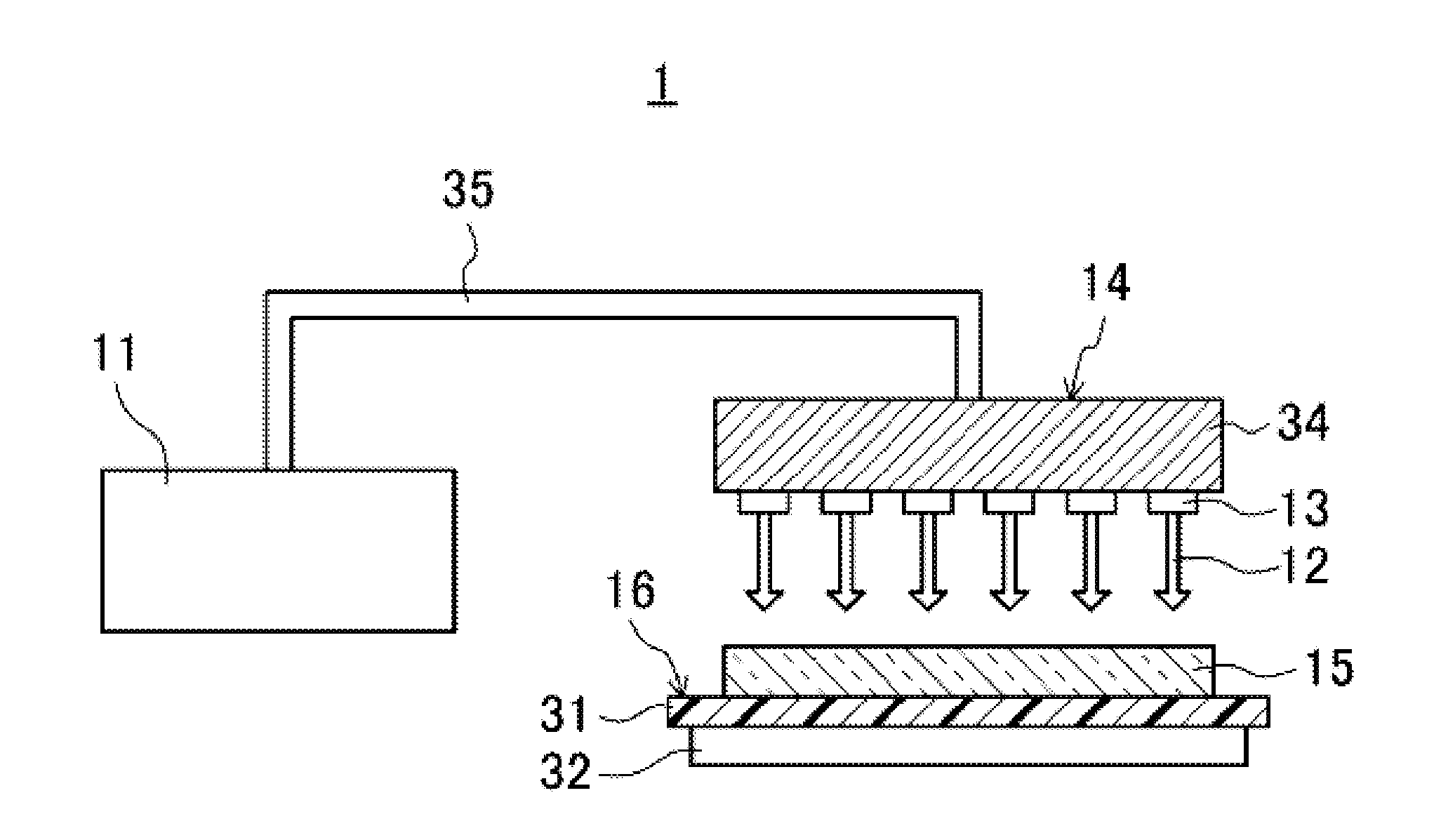
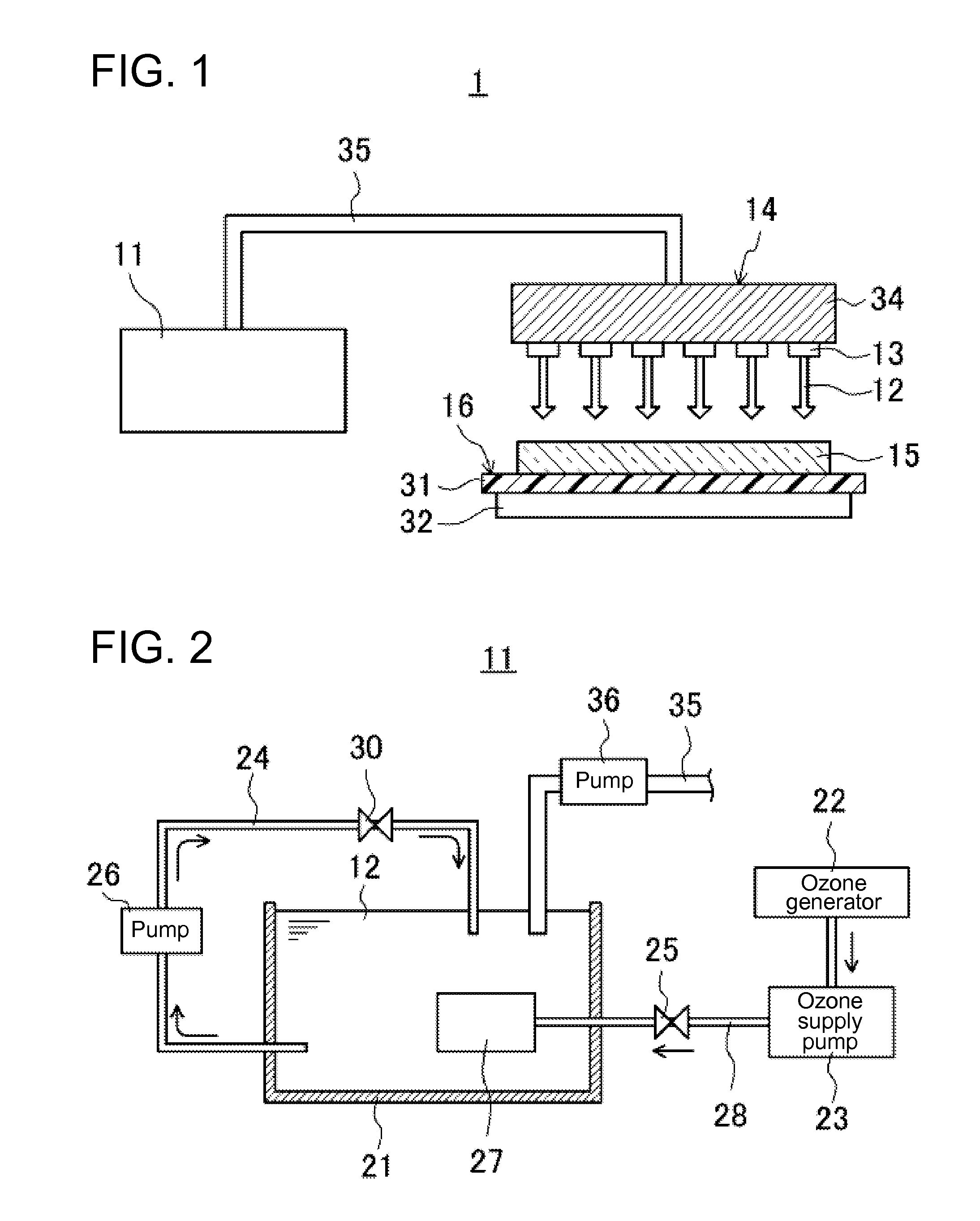
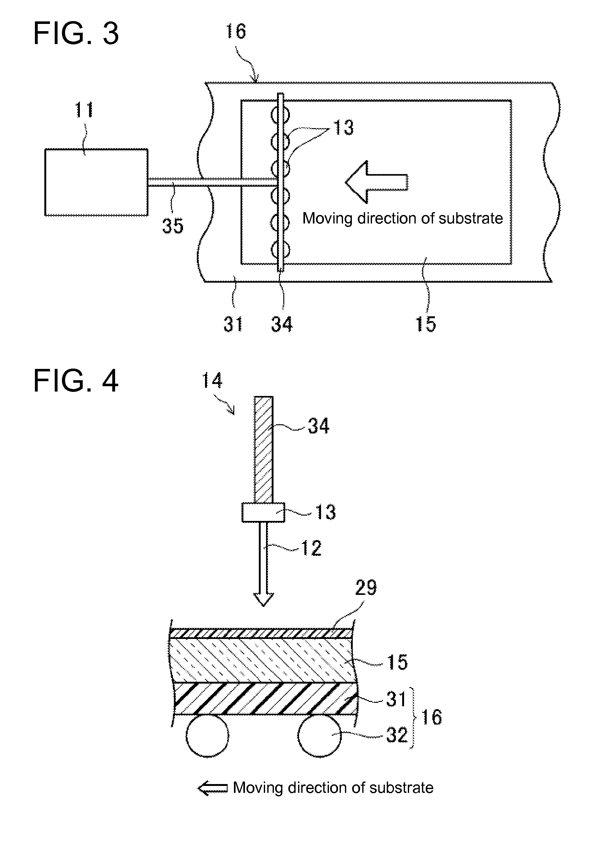
[0064]Here, in Embodiment 1, the substrate to be treated 15 is cleaned by being sprayed with the ozone micro-nanobubble water 12 containing oxidative radicals such as OH radicals, and therefore, the oxidative radicals can be supplied to the substrate to be treated 15 sufficiently. As a result, it is possible to decompose the resist 29 efficiently by only spraying the ozone micro-nanobubble water 12 onto a surface of the substrate to be treated 15, and therefore, the surface of the subst...

embodiment 2

[0066]FIGS. 7 and 8 show Embodiment 2 of the present invention.

[0067]FIG. 7 is a plan view showing a schematic configuration of the substrate cleaning device 1 according to Embodiment 2. FIG. 8 is a cross-sectional view showing an enlarged view of the nozzle header unit 14 according to Embodiment 2. Here, in the following respective embodiments, the members same as those defined in FIGS. 1 to 6 are assigned the same reference characters, and the detailed description of them is omitted.

[0068]In the substrate cleaning device of Embodiment 2, the spray nozzles 13 in the nozzle header unit 14 are positioned differently.

[0069]In other words, as shown in FIGS. 7 and 8, the plurality of spray nozzles 13 are arranged at the nozzle header unit 14 in two lines and in a zigzag shape in a direction perpendicular to the moving direction of the substrate to be treated 15.

[0070]Therefore, according to this Embodiment 2, the plurality of spray nozzles 13 can be arranged densely in the moving direct...

embodiment 3

[0071]FIGS. 9 and 10 show Embodiment 3 of the present invention.

[0072]FIG. 9 is a plan view showing a schematic configuration of a substrate cleaning device 1 according to Embodiment 3. FIG. 10 is a cross-sectional view showing an enlarged view of the nozzle header unit 14 according to Embodiment 3.

[0073]The spray nozzles 13 of the above-mentioned Embodiment 1 were configured so as to spray the ozone micro-nanobubble water 12 in a direction perpendicular to a surface of the substrate to be treated 15, but the spray nozzles 13 of Embodiment 3 are configured so as to spray the ozone micro-nanobubble water 12 in a direction oblique to the surface of the substrate to be treated 15.

[0074]In other words, as shown in FIGS. 9 and 10, the spray nozzles 13 of Embodiment 3 are configured so as to spray the ozone micro-nanobubble water 12 onto a surface of the substrate to be treated 15 in an oblique direction inclined to a side (to the right) opposite to the moving direction of this substrate ...


PUM


Abstract

Disclosed is a substrate cleaning device provided with: a generation unit that generates ozone micro-nanobubble water; a nozzle header unit provided with a plurality of spray nozzles that spray the ozone micro-nanobubble water; and a substrate support unit that supports a substrate to be treated. The surface of the substrate supported by the substrate support unit is cleaned by spraying the ozone micro-nanobubble water from the plurality of spray nozzles onto the substrate.

Description

TECHNICAL FIELD[0001]The present invention relates to a substrate cleaning device and to a substrate cleaning method.BACKGROUND ART[0002]Photolithography is a mandatory step for manufacturing various elements such as TFTs (Thin Film Transistors) and colored layers of a color filter in a prescribed pattern on a substrate configuring a liquid crystal display panel, for example. For example, a resist is applied onto a semiconductor layer, and a resist pattern is formed by a normal photo process. Next, a semiconductor layer exposed from the resist pattern is removed by etching, and then the resist that is no longer necessary is removed to form a prescribed pattern. Circuits and wiring are formed on a substrate by repeating the cycle of applying a resist, forming a resist pattern, etching, and removing the resist as described above.[0003]In a resist stripping step for removing a resist, a mixed solution of sulfuric acid and hydrogen peroxide, an amine organic solvent or the like are used...

Claims


Application Information

Patent Timeline
Patent Type & Authority Applications(United States)
IPC IPC(8): B08B3/08B08B7/04B08B3/02
CPCB08B3/022B08B2203/005H01L27/1259H01L21/67051G03F7/423
Inventor TANAKA, JUNICHIKOHNO, AKIHIKO
Owner SHARP KK
Why Eureka
Try Eureka