Antenna Assembly

Inactive Publication Date: 2012-08-30
LEELARATNE RUS
View PDF4 Cites 4 Cited by
  • Summary
  • Abstract
  • Description
  • Claims
  • Application Information

AI Technical Summary

Benefits of technology

[0012]According to at least one aspect of the present invention, an antenna assembly is provided having an antenna element which resonates at a frequency which is higher than the frequency modulation (FM) range of frequencies for receiving at least one of amplitude modulation (AM), FM and satellite digital audio radio services (SDARS) radio signals. The antenna element is in electrical communication with a printed circuit board which amplifies the radio signals received by the antenna element. A lumped element having a high quality value is disposed on the printed circuit board for increasing the bandwidth of the radio signals received by the antenna element. The antenna element, printed circuit board and lumped element are all disposed within a cover, which can be shaped in an aesthetically pleasing manner, such as for example, a shark fin.
[0013]Since th

Problems solved by technology

However, some people find such antennas to be distracting and visually unappealing.
However, this design also may have its shortcomings as it may interfere with the driver's visibility through the rear windshield or it may interfere with heating (defrosting) elements which may also be embedded within the rear windshield.
Still another type of antenna assembly is a shark fin shaped antenna assembly discussed above, which may be more visually appealing than the elongated rod type of antenna assembly, but may suffer from reduced performance compared thereto and/or may be very costly to manufacture.
Due to the complexity and volume required for this design, the antenna assembly of the '312 application may not be able to effectively receive amplitude modulation (AM) and/or Satellite Digital Audio Radio Service (SDARS) radio signals.
The complexity of this design also may result in relatively high manufacturing costs as compared to other known antenna assemblies.
Fabrication of this coil may be difficult and/or costly due to the high degree of accuracy which is required and the large size required to optimize the performance of the antenna element.
However, obtaining resonance at such frequencies requires that the antenna either be v

Method used


Image

  • Antenna Assembly
  • Antenna Assembly
  • Antenna Assembly

Examples


Example

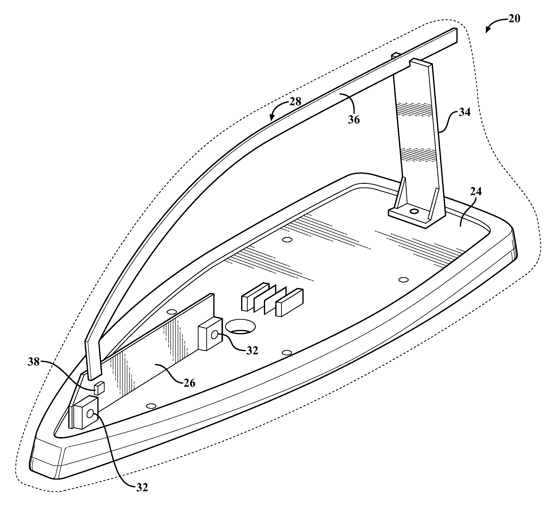
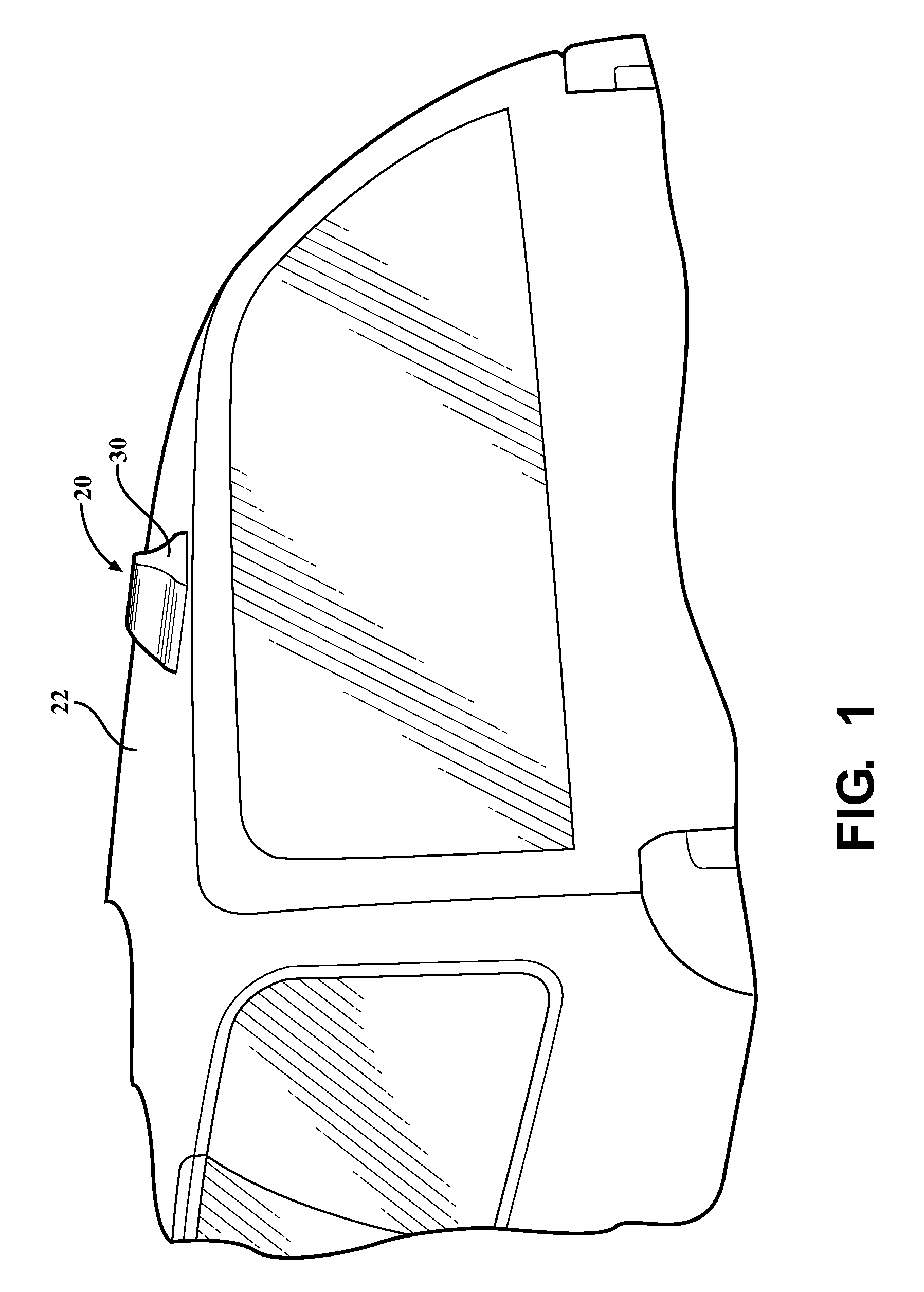
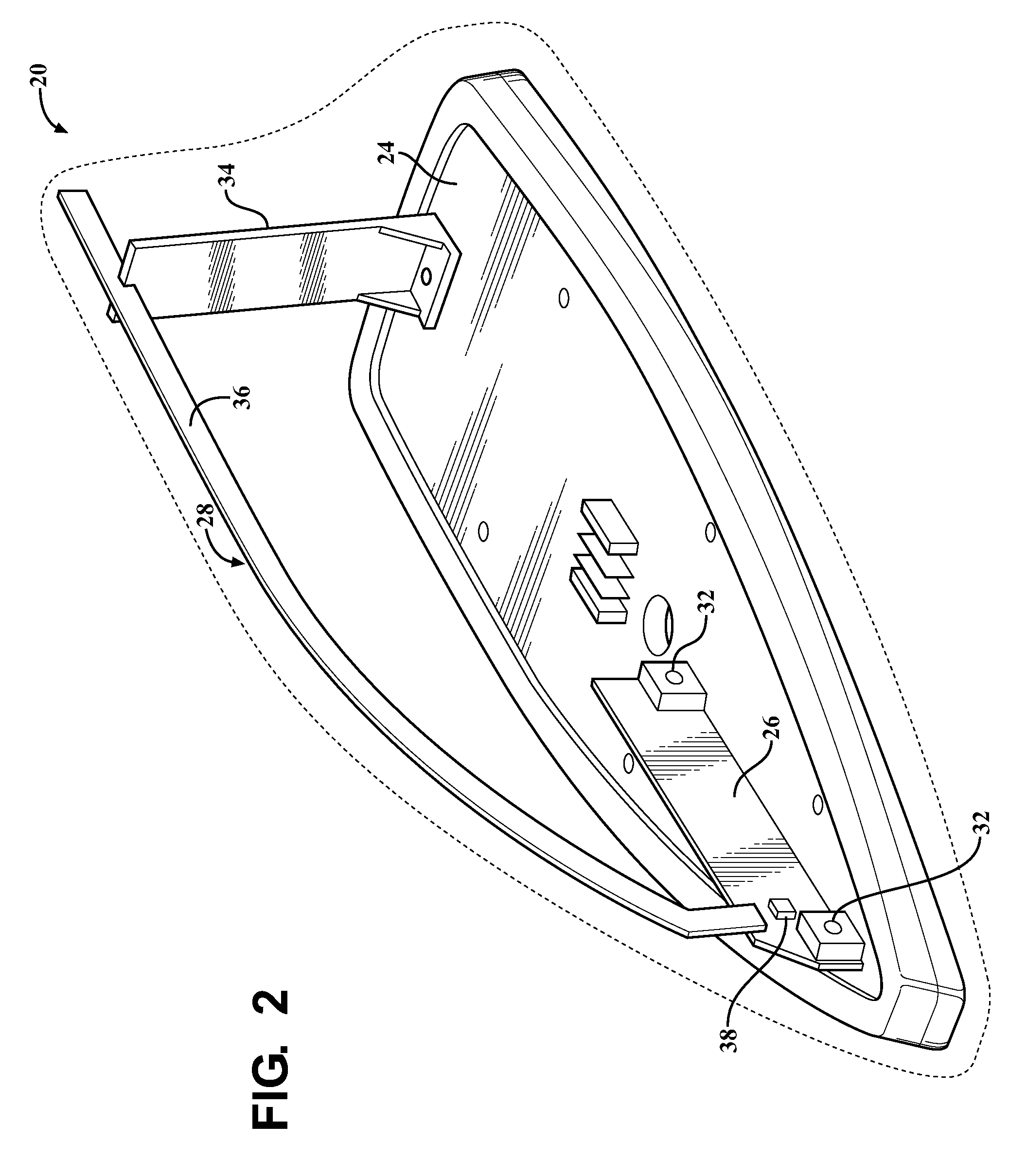
[0018]Referring to the drawings, an exemplary antenna assembly 20 constructed according to at least one aspect of the present invention is generally shown in FIGS. 1 and 2. The antenna assembly 20 is preferably for use on an automobile 22 such as a passenger vehicle, a truck, a bus, etc. However, it should be appreciated that the antenna assembly 20 could find uses in many other vehicular or non-vehicular applications.

[0019]The exemplary antenna assembly 20 includes a ground base 24, a printed circuit board 26, an antenna element 28 and a cover 30. The ground base 24 is preferably of metal and electrically grounded to a metallic component of the vehicle, such as the roof or the trunk. The ground base 24 includes at least one ground post 32 extending upwardly therefrom for receiving and supporting the printed circuit board 26 and at least one support 34 for supporting the antenna element 28. The exemplary support 34 is L-shaped with the short leg being fixed to the ground base 24 and...


PUM


Abstract

An antenna assembly for an automobile including an antenna element having a resonance frequency which is higher than the frequency modulation (FM) range of frequencies for receiving at least one of amplitude modulation (AM), FM and satellite digital audio radio service (SDARS) radio signals. A printed circuit board including amplifier circuitry is in electrical communication with the antenna element for amplifying the radio signals received by the antenna element. A lumped element having a quality value greater than sixty is disposed on the printed circuit board for effectively increasing the bandwidth of radio signals which may be received by the antenna element. All of these components are disposed within a small and aesthetically pleasing cover, such as a shark fin-shaped cover.

Description

CROSS REFERENCE TO RELATED APPLICATIONS[0001]This application claims priority to U.S. Provisional Patent Application Ser. No. 61 / 446,091 filed on Feb. 24, 2011, entitled “Antenna Assembly,” the entire disclosure of the application being considered part of the disclosure of this application and hereby incorporated by reference.BACKGROUND OF THE INVENTION[0002]1. Field of the Invention[0003]The present invention relates to an antenna for a vehicle. More particularly, the present invention relates to an antenna for a vehicle including an antenna element and a printed circuit board amplifier disposed within a cover.[0004]2. Description of the Prior Art[0005]Traditionally, radio antennas are disposed on the exterior of vehicles in plain view of both the driver and others outside of the vehicle. Many of these antennas have an elongated rod-like shape extending upwardly from the front or rear of the vehicle. However, some people find such antennas to be distracting and visually unappealing...

Claims


Application Information

Patent Timeline
IPC IPC(8): H01Q9/04
CPCH01Q9/42H01Q1/3275
Inventor LEELARATNE, RUS
Owner LEELARATNE RUS
Why Eureka
Try Eureka