Three-Level Active Neutral Point Clamped Zero Voltage Switching Converter

a zero-voltage switching converter and neutral-point clamping technology, which is applied in the direction of electric variable regulation, process and machine control, instruments, etc., can solve the problems of limiting switching frequency, reducing switching energy optimally, and unfavorable switching efficiency, so as to achieve high power level conversion and improve efficiency

Active Publication Date: 2012-08-30
VIRGINIA TECH INTPROP INC
View PDF26 Cites 69 Cited by
  • Summary
  • Abstract
  • Description
  • Claims
  • Application Information

AI Technical Summary

Benefits of technology

[0008]It is therefore an object of the present invention to provide a bi-directional power converter of improved efficiency which can provide high power level conversion between AC and DC power

Problems solved by technology

Therefore, there is necessarily an imbalance of losses between inner and outer pairs of switches in a DNPC VSC.
However, while power consumed by the inner switches can be decreased to a degree by using an auxiliary circuit as shown in FIG. 1, the reverse recovery time of the diodes does not provide optimal reduction of switching energy and limits switching frequency such that the potential output power of the converter is also less than optimal.
Further, a major d

Method used


Image

  • Three-Level Active Neutral Point Clamped Zero Voltage Switching Converter
  • Three-Level Active Neutral Point Clamped Zero Voltage Switching Converter
  • Three-Level Active Neutral Point Clamped Zero Voltage Switching Converter

Examples


Embodiment Construction

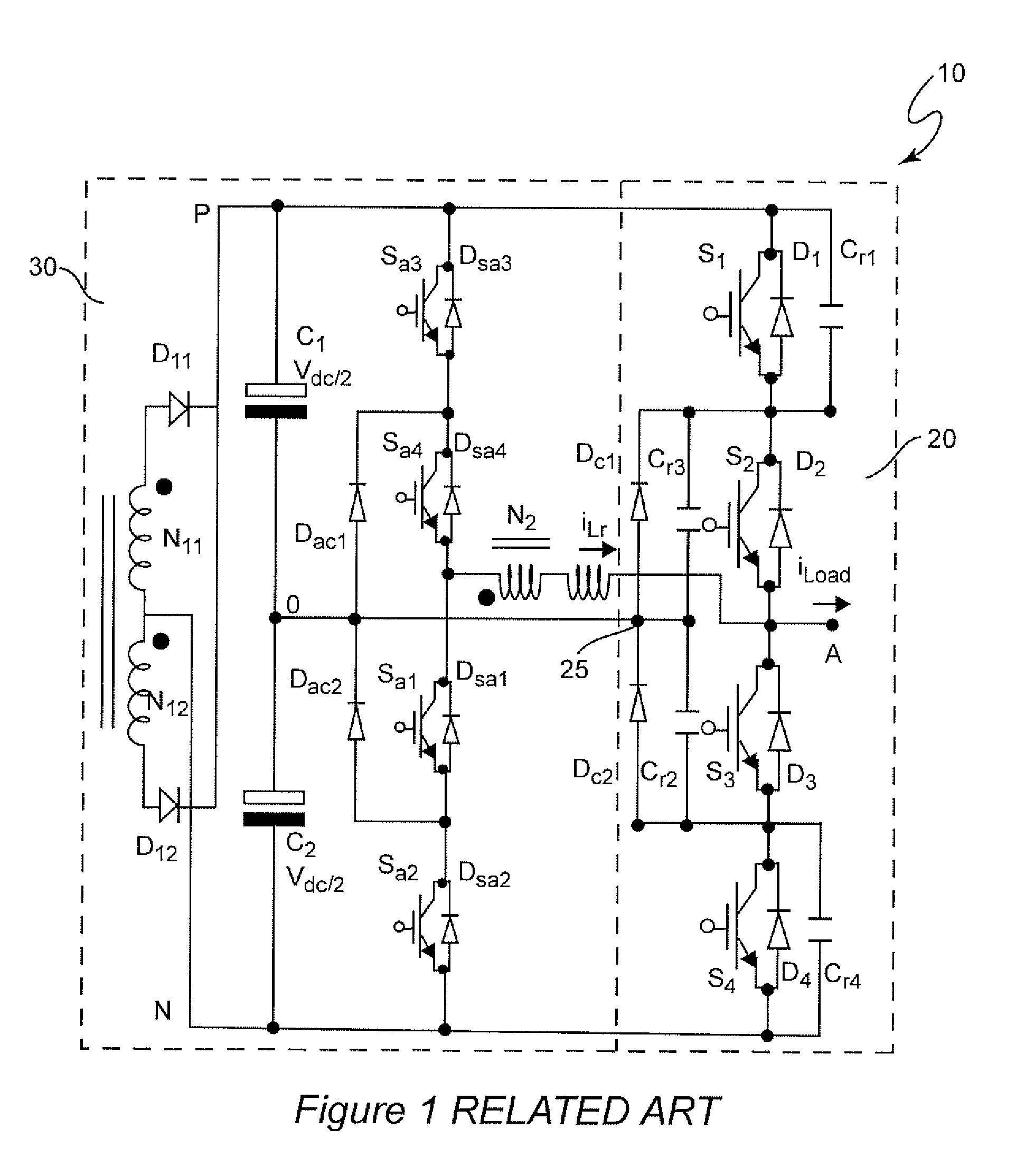
[0025]Referring now to the drawings, and more particularly to FIG. 1, there is shown a schematic diagram of a known and exemplary three-level diode neutral clamped zero voltage switching power converter 10 over which the present invention provides numerous improvements and advantages. It should be understood that while the invention is not depicted in FIG. 1, no portion of the circuit illustrated is admitted to be prior art in regard to the present invention. FIG. 1 has therefore been labeled “Related Art”.

[0026]Three-level diode neutral point clamped (DNPC) voltage source converter (VSC) topologies, of which the circuit 10 of FIG. 1 is an example, have recently become popular for medium voltage and high power applications. Recent studies have also shown that such topologies are attractive and competitive for low voltage, high current applications such as are presented by power requirements for logic circuits and processors of current and foreseeable designs. A converter such as tha...


PUM


Abstract

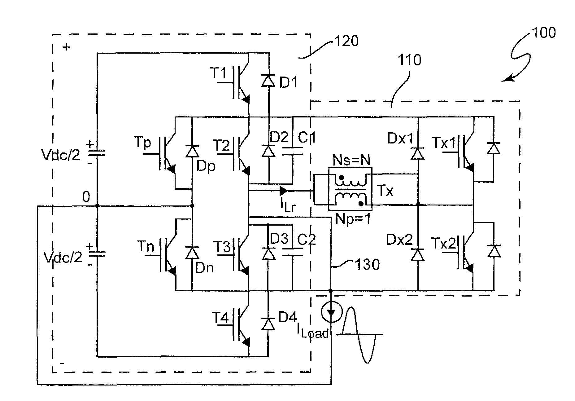
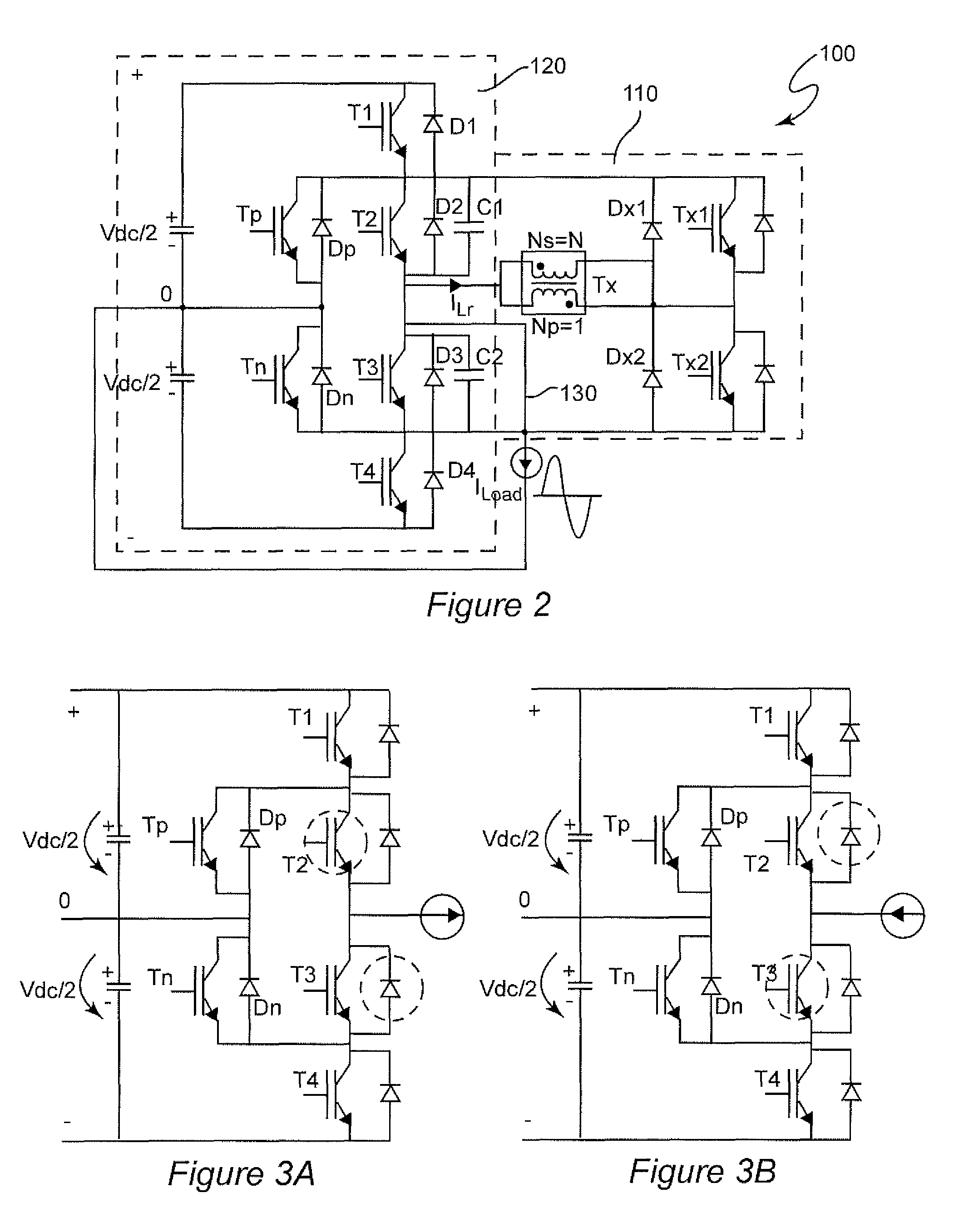
A main circuit of a three-level active neutral point clamped voltage source converter having a pair of additional main switches provides two paths between an output node and a neutral point in which one of the paths involves only switches of an inner pair of switches that are operated at a high frequency. An auxiliary circuit operating at a high frequency for only a brief period during each high frequency switching cycle selects the path involving only the inner switches and provides operation with zero voltage switching and avoids reverse recovery of diodes connected antiparallel with the main and additional main switches. Accordingly, turn-on switching losses in the main switches is avoided and the voltage source converter can be operated at increased frequency to allow reduction in size of magnetic components and full potential power transfer to be achieved.

Description

CROSS-REFERENCE TO RELATED APPLICATIONS[0001]This application claims benefit of priority of U.S. Provisional Application 61 / 446,263, filed Feb. 24, 2011, which is hereby incorporated by reference in its entirety.FIELD OF THE INVENTION[0002]The present invention generally relates to power converter circuits and, more particularly, to bi-directional power converters capable of converting DC to AC or AC to DC power.BACKGROUND OF THE INVENTION[0003]Electrical power is required for operation of a wide variety of devices that provide convenience or answer necessities in many aspects of modern life and human activities. At the present time, electrical power is distributed from locations where it can be conveniently generated to locations where it is utilized as alternating current or voltage (AC) even though many devices, particularly those involving electronic circuits utilize power at a substantially constant voltage referred to as direct current (DC) due to the ability to transmit power...

Claims


Application Information

Patent Timeline
IPC IPC(8): H02M3/335
CPCH02M1/34H02M2001/0058H02M7/487Y02B70/1491H02M2001/342H02M1/0058H02M1/0095H02M1/342Y02B70/10
Inventor LI, JINBOROYEVICH, DUSHANLIU, JINJUN
Owner VIRGINIA TECH INTPROP INC
Why Eureka
Try Eureka