

Ionomer for alkaline fuel cell
a fuel cell and alkaline technology, applied in the field of alkaline fuel cells, can solve the problems of poor mechanical properties, slow oxidation of liquid fuel, and inferior performance and durability of safcs currently used with safcs,
Inactive Publication Date: 2012-09-06
LOS ALAMOS NATIONAL SECURITY
View PDF2 Cites 16 Cited by
- Summary
- Abstract
- Description
- Claims
- Application Information
AI Technical Summary
Benefits of technology
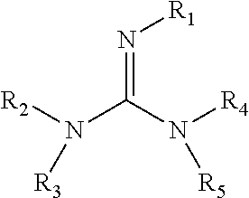
[0014]The invention is also concerned with an anode for an alkaline fuel cell. The anode includes a catalyst and a binder. The binder is a polymeric reaction product of the reaction of a guanidine with apolymer comprising a perfluorosulfonic acid. The guanidine has the formulawherein R1, R2, R3, R4, and R5 are each independently selected from —H, —CH3, —NH2, —NO, —CHnCH3 where n=1-6, HC(═O)—, CH3C(═O)—, NH2C(═O)—, —CHnCOOH where n=1-6, —(CH2)n—C(NH2)—COOH where n=1-6, —CH—(COOH)—CH2—COOH, —CH2—CH(O—CH2CH3)2, —(C═S)—NH2, —(C═NH)—N—(CH2)nCH3, where n=0-6, —NH—(C═S)—SH, —CH2—(C═O)—O—C(CH3)3, —O—(CH2)n—CH—(NH2)—COOH, where n=1-6, —(CH2)n—CH═CH where n=1-6, —(CH2)n—CH—CN where n=1-6, an aromatic group, halide, or halide-substituted methyl group. Anodes prepared with these materials are expected to play a role in minimizing flooding at the anode.
[0015]The invention is also concerned with an alkaline fuel cell comprising an anode that includes a catalyst and a binder, wherein the binder is a polymeric reaction product of the reaction of a perfluorosulfonic acid and a guanidine having the formulawherein R1, R2, R3, R4, and R5 are each independently selected from —H, —CH3, —NH2, —NO, —CHnCH3 where n=1-6, HC(═O)—, CH3C(═O)—, NH2C(═O)—, —CHnCOOH where n=1-6, —(CH2)n—C(NH2)—COOH where n=1-6, —CH—(COOH)—CH2—COOH, —CH2—CH(O—CH2CH3)2, —(C═S)—NH2, —(C═NH)—N—(CH2)nCH3, where n=0-6, —NH—(C═S)—SH, —CH2—(C═O)—O—C(CH3)3, —O—(CH2)n—CH—(NH2)—COOH, where n=1-6, —(CH2)n—CH═CH where n=1-6, —(CH2)n—CH—CN where n=1-6, an aromatic group, halide, or halide-substituted methyl group. These materials are expected to play a role in minimizing flooding at the anode of these fuel cells during operation.
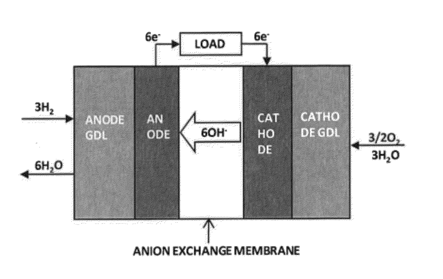
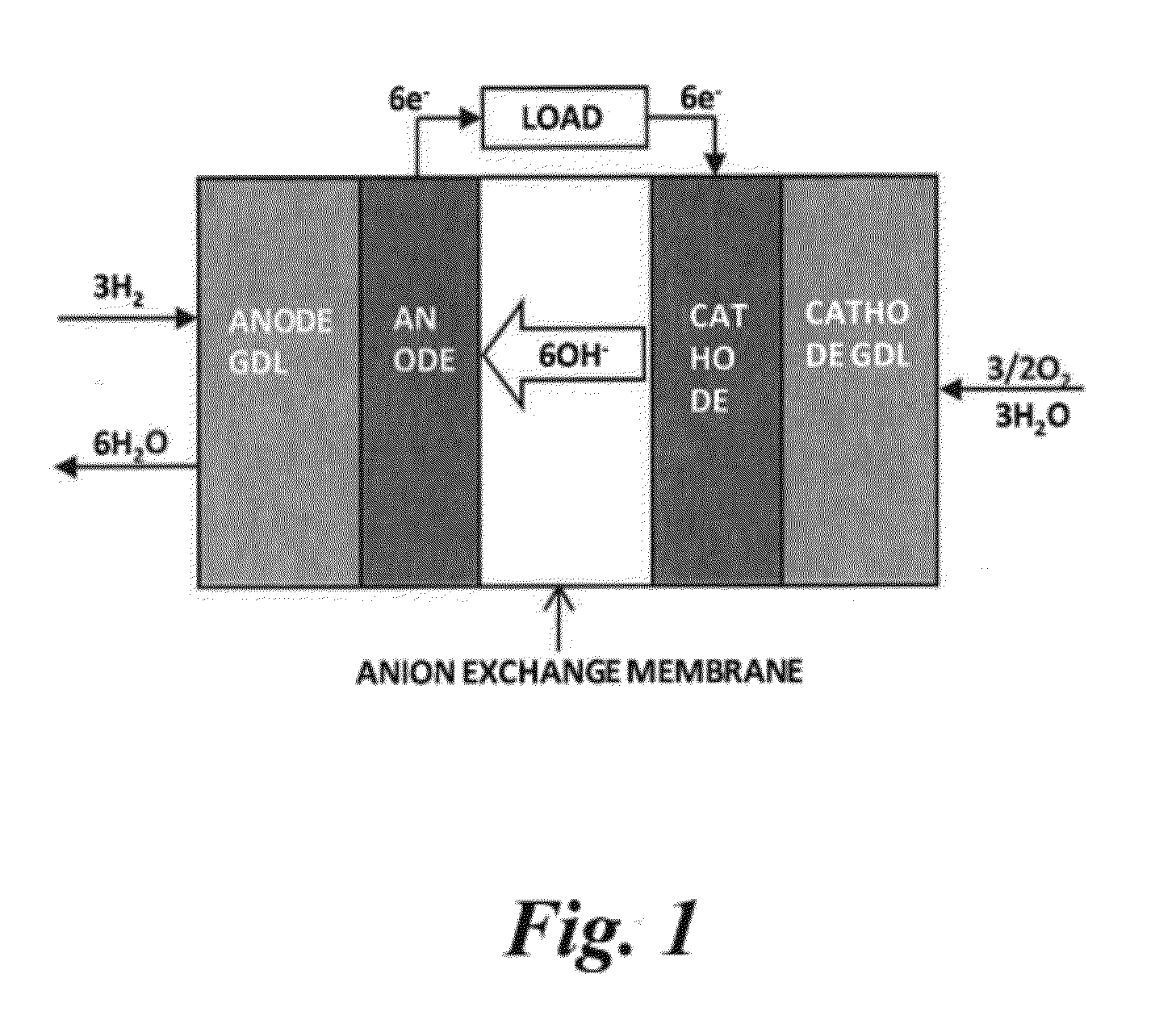
[0016]The invention is also concerned with an alkaline fuel cell comprising an anode that is a hydrogen electrode, an anion conducting membrane, and a cathode that is an oxygen electrode. The anode is a composite including an electro-catalyst (50 to 90 weight percent) for hydrogen oxidation and a binder (10 to 50 weight percent). The binder is a polymeric reaction product of a reaction between a perfluorosulfonic acid polymer composition and an amine such as a guanidine having the formulawherein R1, R2, R3, R4, and R5 are each independently selected from —H, —CH3, —NH2, —NO, —CHnCH3 where n=1-6, HC(═O)—, CH3C(═O)—, NH2C(═O)—, —CHnCOOH where n=1-6, —(CH2)n—C(NH2)—COOH where n=1-6, —CH—(COOH)—CH2—COOH, —CH2—CH(O—CH2CH3)2, —(C═S)—NH2, —(C═NH)—N—(CH2)nCH3, where n=0-6, —NH—(C═S)—SH, —CH2—(C═O)—O—C(CH3)3, —O—(CH2)—CH—(NH2)—COOH, where n=1-6, —(CH2)n—CH═CH where n=1-6, —(CH2), —CH—CN where n=1-6, an aromatic group, halide, or halide-substituted methyl group. These materials are expected to play a role in minimizing flooding at the anode of these fuel cells during operation.
Problems solved by technology
PEFCs require expensive precious metals (e.g. platinum) as electrocatalysts, and operate under acidic conditions, for which the oxidation of the liquid fuel is slow.
The performance and durability of SAFCs currently is inferior to that for PEFCs.
Anion exchange polymer membranes currently used with SAFCs tend to exhibit lower ion conductivity, have poorer mechanical properties, and degrade faster under fuel cell operating conditions than cation exchange polymer membranes used with PEFCs.
There are also problems associated with the electrodes.
A significant loss in fuel cell performance is due to flooding (i.e. slow removal of accumulated water) which limits gas diffusion.
This has resulted in a decrease in ionic conductivity in the catalyst layer.
Fluorinated binders have generally not been utilized with SAFCs in the past because fluorinated polymers are not stable under alkaline conditions.
However, the synthesis of these polymer electrolytes requires complex multi-step polymerization chemistry, and the solubility of the resultant materials is poor, which limits the electrode processing capabilities.
Method used
View moreImage
Smart ImageViewing Examples

Examples
example 1
[0031]Ionomer preparation: A perfluorosulfonic acid polymer (NAFION®) membrane was immersed in a solution of 1,1,3,3-tetramethylguanidine (TMG) for 2 hours. Then, the membrane was repeatedly soaked in pure water enough to remove excess amine.
example 2
[0032]Ionomer preparation: A perfluorosulfonic acid polymer (NAFION®) membrane was dissolved in a solution of NMP. The solution of 1,1,3,3-tetramethylguanidine (TMG) was added into polymer solution. Then, this polymer solution was cast on a glass plate and dried. The membrane was repeatedly soaked in pure water enough to remove excess amine.
example 3
[0033]Dispersion preparation: An embodiment ionomer is dissolved in a solution containing 2.5 wt percent NMP.
Login to View More PUM
| Property | Measurement | Unit |
|---|---|---|
| Polymeric | aaaaa | aaaaa |
Abstract
An ionomer may be used as a binder for a catalyst to prepare an anode for a solid alkaline fuel cell. The ionomer is a reaction product of a guanidine and a perfluorosulfonic acid polymer.
Description
RELATED APPLICATIONS[0001]This application claims the benefit of U.S. Provisional Application No. 61 / 448,834 entitled “Ionomer for Alkaline Fuel Cell,” filed Mar. 3, 2011, hereby incorporated by reference.STATEMENT REGARDING FEDERAL RIGHTS[0002]This invention was made with government support under Contract No. DE-AC52-06NA25396 awarded by the U.S. Department of Energy. The government has certain rights in the invention.FIELD OF THE INVENTION[0003]The present invention relates to alkaline fuel cells (“AFCs”), and more particularly to ionomers that may be used as catalyst binders for anodes in AFCs.BACKGROUND OF THE INVENTION[0004]Fuel cells convert the chemical energy of fuel into electrical energy. Polymer electrolyte fuel cells (“PEFCs”) and alkaline fuel cells (“AFCs”) are well known examples of fuel cells. PEFCs have a relatively simple cell design and use a liquid fuel (e.g. methanol, ethanol, ethylene glycol, glycerol, dimethyl ether, hydrazine, and the like) that can be easily...
Claims
Login to View More Application Information
Patent Timeline
 IPC IPC(8): H01M4/62H01M4/92H01M4/90C08J5/22H01M8/10
CPCH01M8/083H01M4/622C08J5/2293C08J2327/18Y02E60/50Y02E60/10
InventorKIM, YU SEUNGKIM, DAE SIK
OwnerLOS ALAMOS NATIONAL SECURITY