
Sun tracking control system for solar collection devices

a solar energy collection and control system technology, applied in solar heat systems, instruments, lighting and heating apparatus, etc., can solve the problems of system easily fooled, limited pointing accuracy, and limiting the ultimate efficiency of one (1) axis trackers by several percent, and achieves the effect of inexpensive maintenance and inexpensive manufacturing

Inactive Publication Date: 2012-09-13
ADVANCED TECH & RES CORP
View PDF4 Cites 26 Cited by
  • Summary
  • Abstract
  • Description
  • Claims
  • Application Information

AI Technical Summary

Benefits of technology

[0011]The microprocessor uses an embedded Global Positioning System (GPS) circuit to accurately determine the system location, date, and time of day. This information is available upon power up and provides the tracking system with all the necessary information and does not require any manual data input during the initialization procedure. The initialization function is automatic.
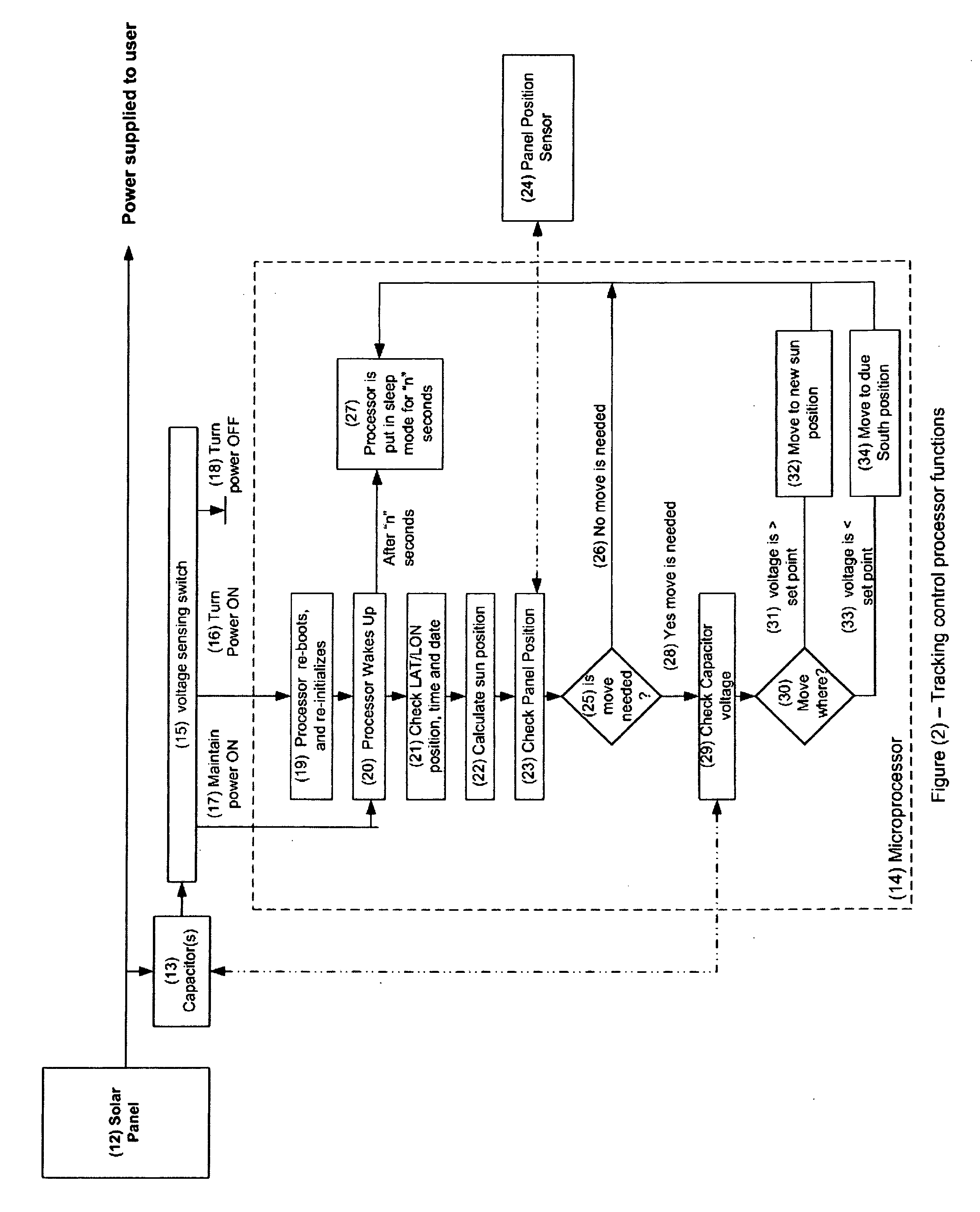
[0020]The control system of this invention plans on the regular loss of power to the controller and the orderly re-initialization of functions when power is returned. This will happen every day as the sun sets and the power drops through the pre-programmed threshold and the panel(s) will be positioned to the due South position. The due South position is chosen since this is the optimum position for fixed panels. Without sufficient sunshine the power will continue to drop until the processor shuts down leaving the panel(s) pointed in the due South position. When sufficient sunshine returns, the processor will turn back on, all systems will re-initialize and the solar array will drive to the current calculated position of the sun. This regular and periodic “re-boot” of the system controller has a purging and self correction effect to automatically fix any system anomalies on a frequent and regular basis.
[0022]The object of this invention is to provide a solar tracking controller that can be powered directly from a solar array and exhibits a robust and self correcting logic.
[0025]A further object of this invention is to provide a solar tracking controller that is inexpensive to manufacture.
[0026]A further object of this invention is to provide a solar tracking controller that is inexpensive to maintain.
[0028]A further object of this invention is to provide a solar tracking controller that does not require battery storage to provide power or maintain volatile memory or setup parameters.

Problems solved by technology

A typical one (1) axis tracker follows the same path every day and does not automatically accommodate the changes in the elevation of the sun path as it changes throughout the year.
This small pointing error limits the ultimate efficiency of one (1) axis trackers by several percent.
The shading fixture is physically configured such that the outputs are balanced when pointed at the sun and unbalanced when pointed off-axis to the sun.
However, the pointing accuracy is limited and the system can be easily fooled on partly cloudy days, extraneous lighting, and the ambiguity of where to go at the end of the day.
These “balancing” systems are also not very energy efficient.
These systems are more energy efficient and cannot be fooled by optical sensors.
However they are also very susceptible to power outages, power surges, and a host of other conditions that can interrupt the proper functioning of the control processor.
Battery life is highly unpredictable and even a temporary failure will cause the tracking system to stop working and require some sort of restart procedure.
Recovery can be difficult if the panel was stopped in a bad position and re-starting may require a technician with advanced skills and tools to travel to a remote site for servicing.

Method used


Image

  • Sun tracking control system for solar collection devices
  • Sun tracking control system for solar collection devices
  • Sun tracking control system for solar collection devices

Examples


Embodiment Construction

[0036]The following sections describe only one embodiment of this invention where the application is for a solar panel tracking system. It should be obvious that this invention could be utilized in other applications where a control processor is powered from an electrical source that is variable and has a wide range in outputs including 0 volts.

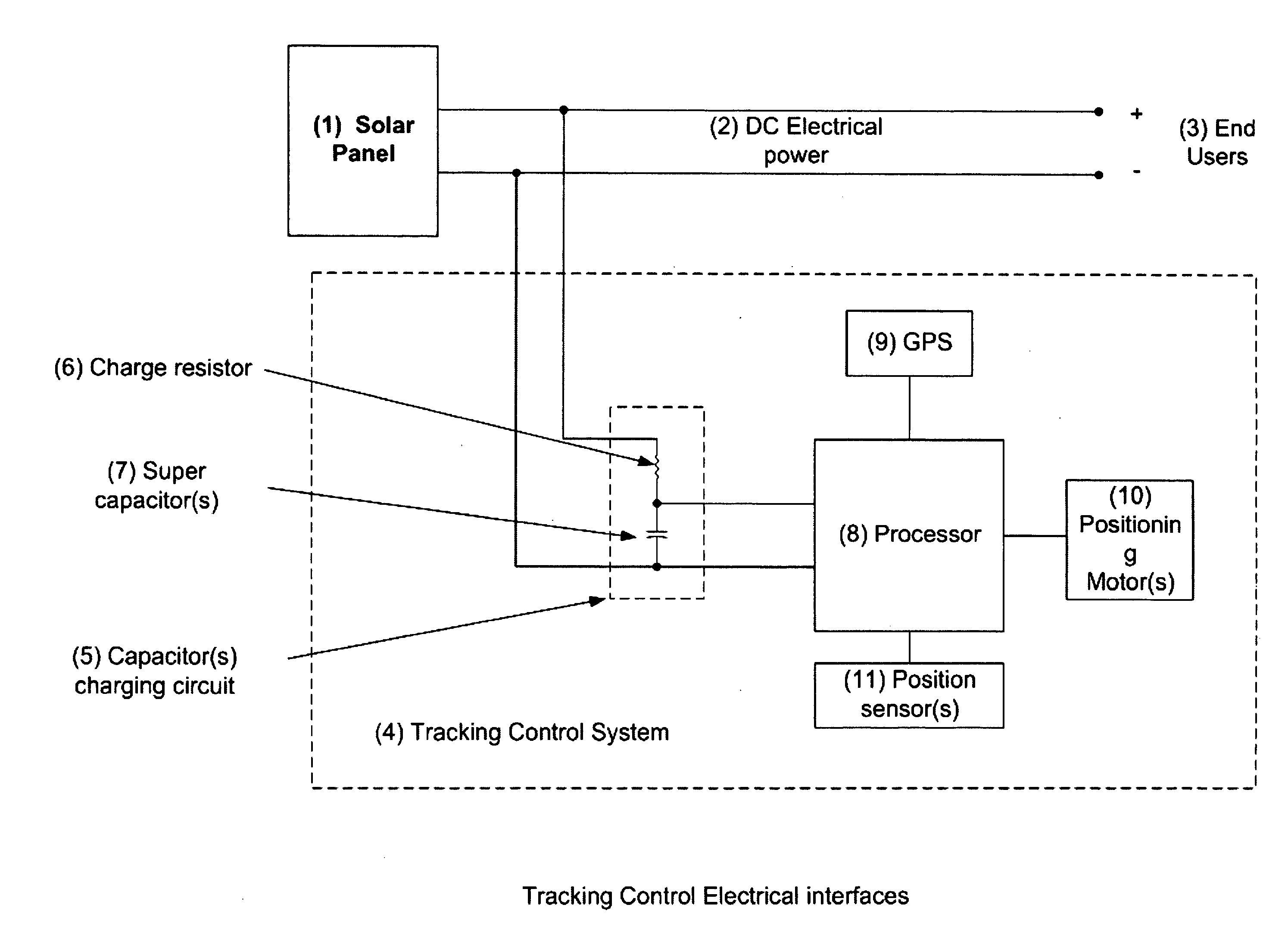
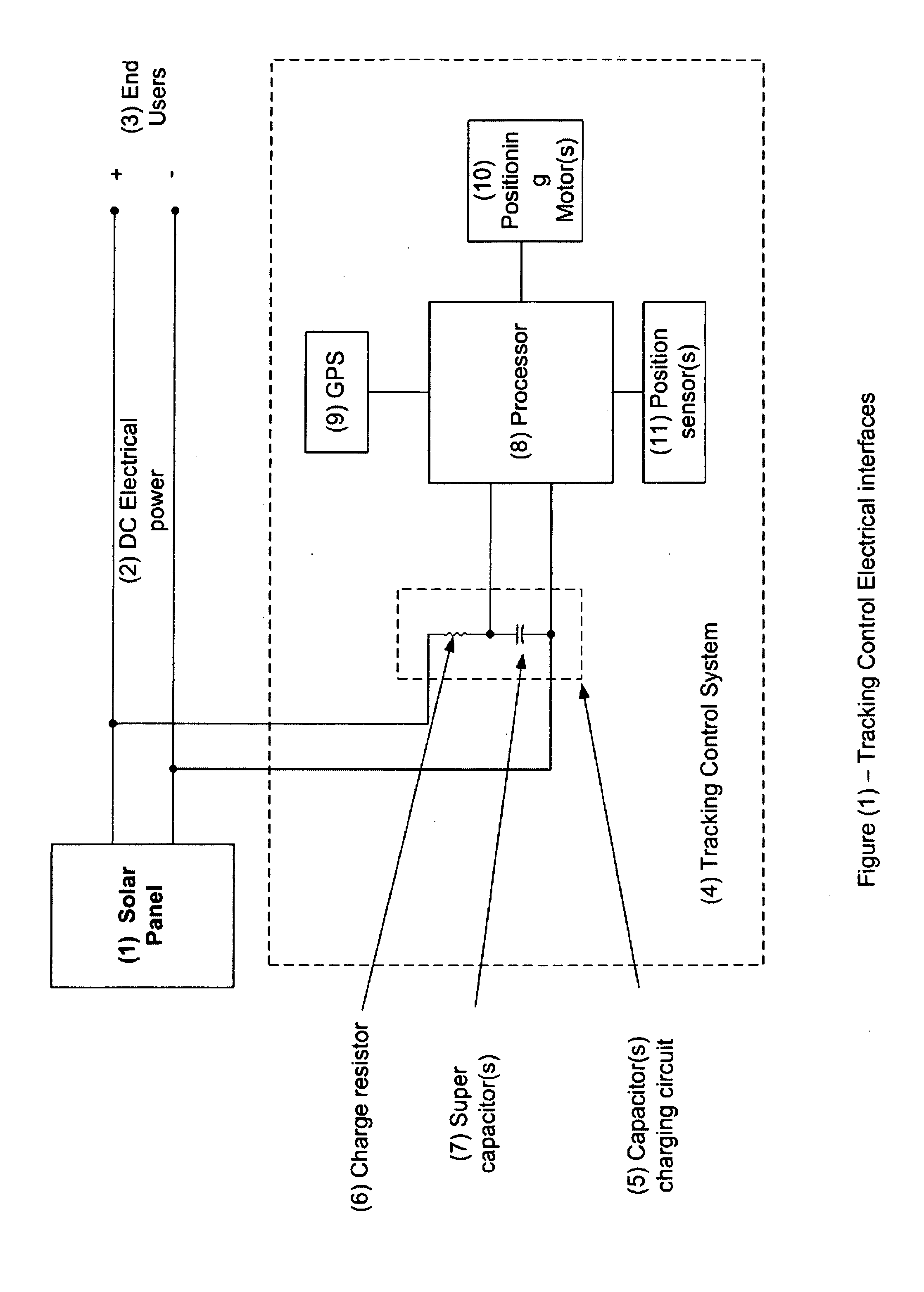
[0037]FIG. 1 shows how the tracking control electronics interface with a solar panel to share the generated power. The solar panel (1) is producing DC electrical power (2) to the end user (3). The tracking control system (4) receives its power by tapping into the output of the solar panel (1). Inside the tracking control system (4) is a capacitor(s) charging circuit (5). The charge resister (6) limits the current flow across the capacitor (7) to safely charge it up to its maximum voltage.

[0038]The tracking control is performed by the microprocessor (8) which is connected to the capacitor(s) (5) as its power source. The microprocessor (8) is a...


PUM


Abstract

This invention presents a robust design for a sun tracking control system where a capacitor(s) is charged from the solar panel and used to power a tracking control system and motor actuator(s). The control system periodically moves the solar array to a calculated sun position. The control system also monitors the energy stored in the capacitor(s) and makes its move decisions contingent on the level of stored energy. This added level of energy based decisions provide the tracking system a robust operating behavior to accommodate real world operating conditions with a simple rule set.

Description

BACKGROUND OF THE INVENTION1. Field of the Invention:[0001]This invention relates to sun tracking solar energy collection systems and specifically to the design of a tracking control system that is self powered, robust, and adaptive to different changing sun conditions.[0002]2. Brief Description of Prior Art[0003]Sun tracking is a common technique used to increase the energy yield of solar energy collection systems. Many such devices are described in prior art and nearly all of them can be classified as one (1) or two (2) axis trackers depending on the different freedom of movements of their tracking mechanism.[0004]The equatorial mount is a common example of a one (1) axis tracker where the solar array is rotated around a single axis that is oriented parallel to the earth's rotational axis. The rotation of the solar array is controlled to match the rotation of the earth so that the solar array tracks the sun as the sun moves from East to West throughout the day. A typical one (1) a...

Claims


Application Information

Patent Timeline
IPC IPC(8): F24J2/40F24J2/38F24S50/20
CPCF24J2/38G01S19/14Y02E10/47F24S50/20
Inventor LUNDAHL, ROBERT D.CUTLIP, ROBERT WESLEYSELZLER, MICHAEL
Owner ADVANCED TECH & RES CORP
Learn More