Fluid resistance reducing method and resistance reducing propulsion device

a technology of fluid resistance and resistance reduction, applied in water installations, circuit elements, thin material processing, etc., can solve the problems of limited resistance reduction effect, high polymer price, and high cost of high-polymer materials, so as to reduce shaped resistance and fluid resistance efficiently, improve the effect of resistance reducing propulsion devi

Inactive Publication Date: 2012-09-13
ZOU LISONG
View PDF4 Cites 2 Cited by
  • Summary
  • Abstract
  • Description
  • Claims
  • Application Information

AI Technical Summary

Benefits of technology

[0008]An object of the present invention is to overcome the above disadvantages and provide a fluid resistance reducing method and its resistance reducing propulsion device based on an improvement to “method for reducing fluid resistance and apparatus for the same” in the invention of PCT / CN2006 / 001825 recited in the description of related arts, wherein the improved resistance reducing method is added with a new ability to reduce shaped resistance efficiently and has typical application devices respectively in fields of internal flow manner, external flow manner and rotating flow manner; the accordingly improved “resistance reducing propulsion device with multiple movable walls” for reducing fluid frictional resistance forms a complete system to produce more compact practical application products in various application fields, so as to be fit for relatively small pipes and channels, to adapt to operation on curved surfaces and become thinner, to better resist unbalanced forces, to omit most rotating components fixed on original positions such as bearings and rolling cylinders for convenient maintenance and to replace various conveyors in various places. The resistance reducing method and its resistance reducing propulsion device of the present invention are able to efficiently reduce the fluid frictional resistance and the shape resistance including other similar resistance, to be widely applied in fields including water conservancy, aviation, navigation, underwater sports, transportation, national defense and pipeline transportation for reducing fluid resistance and to propel or add pressure.

Problems solved by technology

However, practical technology and technological measures of replacing viscous fluids having quite different viscosity and specific gravity on all the boundaries remain to be completely solved, and thus promotion thereof is difficult.
However, high polymers are expensive and readily ineffective under shearing forces.
Resistance reduction effects thereof are limited.
The fourth category derives from bionics, but has limited resistance reduction effects.
However, this technology is nearly forgotten because of difficulty in realization and practical application and technical solutions thereof have limited effects of reducing resistance.
The manual intervention device is ineffective in reducing the shaped resistance no matter in the condition of external flow manner or in the condition of internal flow manner, except working as a propeller, when the pressure difference between the head and the tail is partially reduced by suction effect, which is similar to water jet propulsion, and thus the loss usually outweighs the gains.
Furthermore, in the condition of external flow manner, the operating environment is always quite harsh, while the device seldom has a big resistivity to the unbalanced pressure vertical to the moving direction thereof because the flexible films of the “movable boundary” has no hole and thus the counter-flow area is relatively large.
In the practical application, the unbalanced pressure such as a slightly huge wave and slightly large airflow is able to deform the “movable walls” to produce contact frictions even to destroy the operation of the device.
If a “caterpillar belt” is used or rolling cylinders are densely arranged to form a stream line, mechanical resistance may be increase and a series of problems can be caused.
In the condition of internal flow manner, a large number of rotating components including bearings and rolling cylinders are used, and these rotating components are readily damaged and needs plenty of maintenance.
Most of these rotating components are fixed on the original positions, and even the movable flexible films are limited on a certain area, so it is difficult to repair.
For example, frequently opening an oil pipeline or a coal water mixture pipeline of hundreds of kilometers long or a long-distance water transferring pipeline to repair various components in fragments, and adding lubricant oil on the bearings are both unacceptable in practical operations.
In the condition of internal flow manner, many components are provided inside pipes and channels having narrow space and thus effective flow area is further reduced, which further limits the application.
Moreover, the internal flow pipe or channel is not always straight and inevitably has many turnings, ascents and descents.
If each turning is formed by jointing several straight portions, not only partial loss is not reduced but also new partial resistance is caused; if the fluid therein is accelerated, despite the fact that a part of frictional resistance can be reduced, newly caused partial resistance is so considerable that the internal flow pipe or channel is unfit for the practical application.
Many other problems also exist.

Method used


Image

  • Fluid resistance reducing method and resistance reducing propulsion device
  • Fluid resistance reducing method and resistance reducing propulsion device
  • Fluid resistance reducing method and resistance reducing propulsion device

Examples


first preferred embodiment

[0084]According to the first preferred embodiment of the present invention, a rotating flow separator improved by the present invention has a diameter of 1 m and a cross section as showed in FIG. 12, wherein five to ten pieces of resistance reducing films having many holes are provided along an internal wall and several courses are provided on each movable wall whose sum of thickness and an interval equals 1 cm, totally 5 cm to 10 cm; wherein 40 straight vanes as thick as 2 mm are provided and connected to a power supplying device through a rotation axle to drive fluid to rotate and separate at a high speed. Thus separator not only has reduced energy consumption but also reduced wear between the fluid and container wall, so as to break limitation of small size.

second preferred embodiment

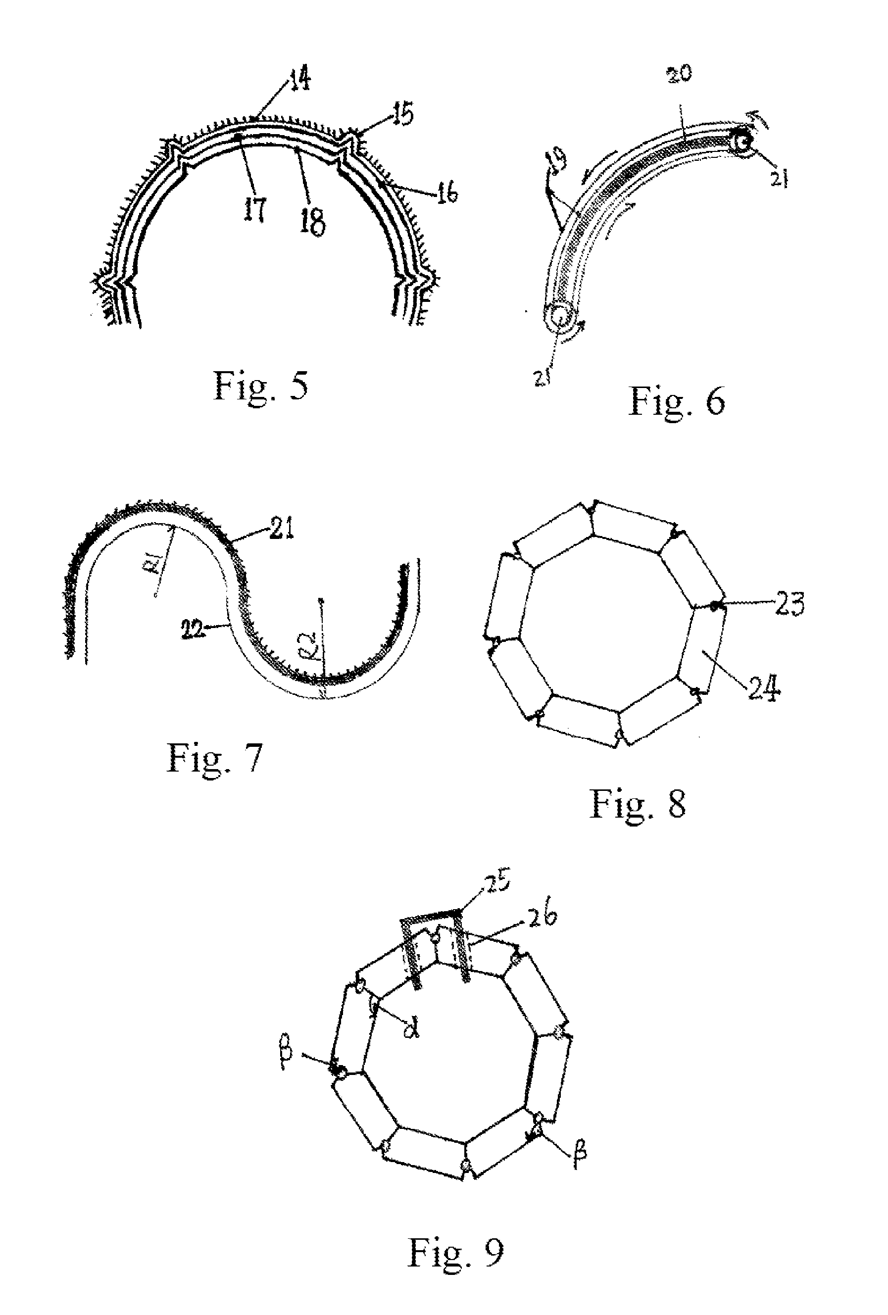
[0085]A water conveying pipeline connecting two places is needed. The pipeline is 80 km long; a height difference is about 12 m; the pipe has a diameter of 2 m. The pipe has a section as showed in FIG. 22. Twenty resistance reducing films are provided along internal wall. Thirty courses are provided on each film and its base. A sum of thickness of each resistance reducing film and an interval therebetween equals 5 mm, totally 10 cm long. Four positioning courses are provided. Each rigid frame as showed in FIG. 8 and FIG. 9 is provided on internal pipe at an interval of 1 m. Each straight vane, as high as 10 cm, is provided on the internal pipe at an internal of 50 cm. The vane groups can be separated with the internal pipe. The smallest turning radius of the pipeline is controlled more than 200 m. Because frictional resistance and partial resistance are basically eliminated, the water is able to move 10 m / s. The internal pipe and the resistance reducing films are opened at the desti...

fourth preferred embodiment

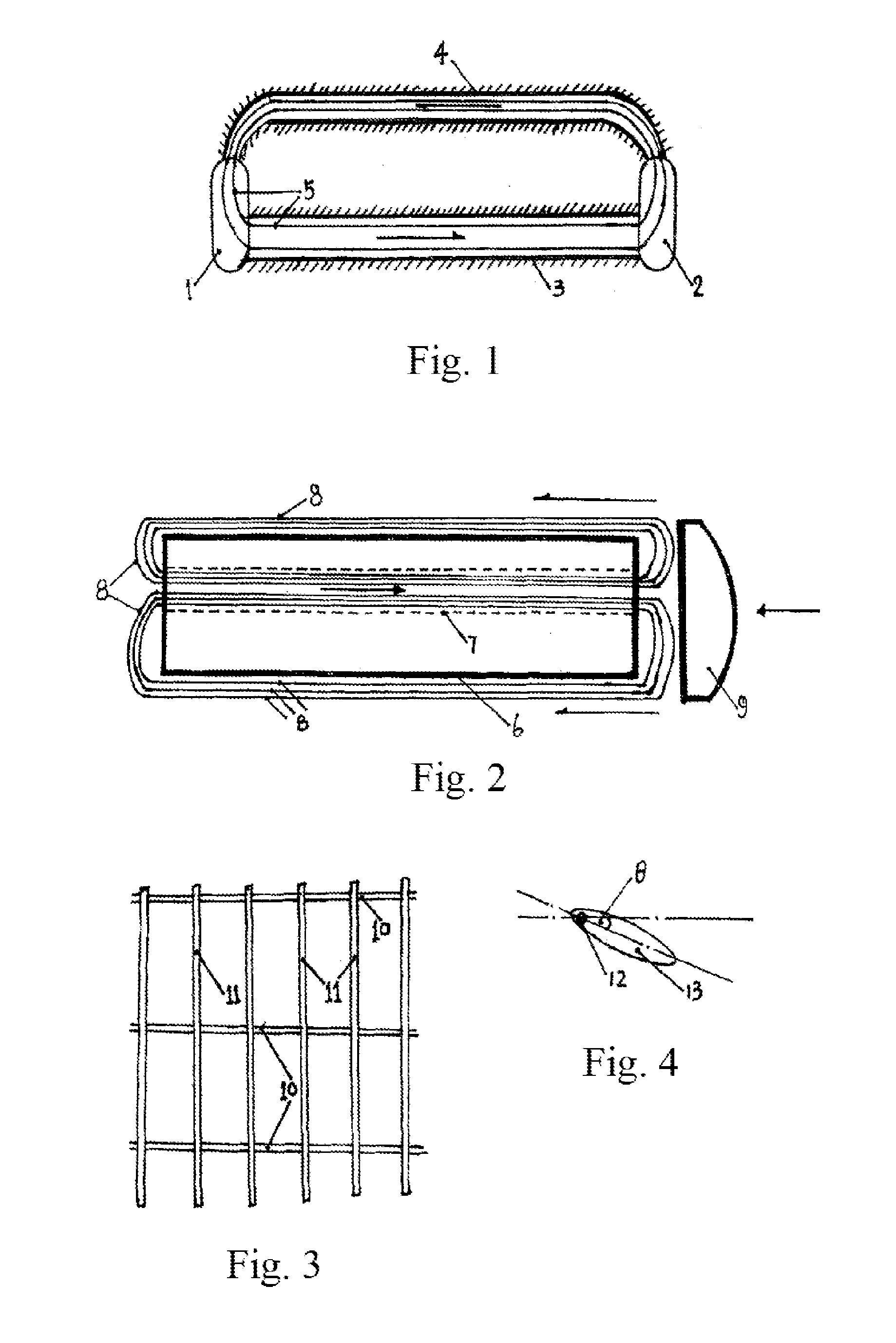
[0087]A new ship, according to the fourth preferred embodiment of the present invention, breaks a limitation of stream lines. The ship body is cubic, as showed in FIG. 2. The ship is 12 m wide, 6 m high and around 120 m long. Around 20 resistance reducing films are installed thereon to reduce frictional resistance. 200 courses are provided on each resistance reducing film and its base. A sum of thickness of each film and an interval therebetween is 5 mm, totally 10 cm. Each resistance reducing film uses a telescopic grate-shaped element as showed in FIG. 10 to limit a possibly stretching range to produce a rigid cross section as showed in FIG. 27. A return path, provided inside the ship body, is a rectangular channel having a diameter of 2 m. Permanently magnetic suspension systems are also provided along the whole circulation path to expand or to tighten, in such a manner that longitudinal sections are stable and able to resist wave pressure. Runners of counter-flow resistance redu...


PUM


Abstract

A fluid resistance reducing method and a resistance reducing propulsion device are disclosed, wherein vane-shaped devices are inserted in the fluid at a certain interval along a vertical direction to a moving velocity direction of the fluid, and thus the fluid is divided into several limited zones to limit the fluid and solidify moving state; resultantly the fluid is prevented from directly crashing with fixed wall of a surface of an object to be resistance-reduced and thus a moving velocity direction of the vane-shaped device accords with a predetermined direction of a tangent line of the fixed wall and reaction force on the fluid provides a centripetal force for the fluid to turn, so as to force the fluid to gradually change the velocity direction along the fixed wall and manually intervene with parts of the object to force the fluid near a boundary face to moves stratifiedly and orderly.

Description

CROSS REFERENCE OF RELATED APPLICATION[0001]This is a U.S. National Stage under 35 USC 371 of the International Application PCT / CN2010 / 078732, filed Nov. 15, 2010.BACKGROUND OF THE PRESENT INVENTION[0002]1. Field of Invention[0003]The present invention relates to a method for reducing fluid resistance including frictional resistance, viscous pressure resistance and similar resistances and propelling (adding pressure), and typical application devices realized in multi-fields.[0004]2. Description of Related Arts[0005]In the long term search for fluid resistance reducing methods, attention is only focused on and limited to the shape, i.e., an exploration of streamlines of objects. Air resistance reduction designs of high-speed trains, missiles, automobiles and etc. still remain on this stage. After the establishment of boundary layer theory and several years' development, conventional resistance reducing methods are divided into four categories based on different ways of reducing visco...

Claims


Application Information

Patent Timeline
Patent Type & Authority Applications(United States)
IPC IPC(8): F15C1/06
CPCF15D1/02F15D1/007F15D1/10Y10T137/0318Y10T137/2224
Inventor ZOU, LISONG
Owner ZOU LISONG
Why Eureka
Try Eureka