Switched capacitor circuit

a technology of switching capacitors and capacitors, applied in the field of switching capacitor circuits, can solve the problems of high power consumption and large area of the op-amp, and achieve the effect of reducing power consumption and an area occupied, removing offset and flickering nois

Active Publication Date: 2012-09-13
IND ACADEMIC CORP FOUND YONSEI UNIV
View PDF2 Cites 19 Cited by
  • Summary
  • Abstract
  • Description
  • Claims
  • Application Information

AI Technical Summary

Benefits of technology

[0020]According to the present invention, a switched capacitor circuit may reduce power consumption and an area occupied by the switched capacitor circuit while extending a range of applications of a semiconductor circuit, using an inverting amplifier including a chopper stabilization circuit to remove an offset and a flicker noise.

Problems solved by technology

However, the OP-Amp. has issues in terms of high power consumption and occupying a large area.

Method used


Image

  • Switched capacitor circuit
  • Switched capacitor circuit
  • Switched capacitor circuit

Examples


Embodiment Construction

[0027]Reference will now be made in detail to embodiments of the present invention, examples of which are illustrated in the accompanying drawings, wherein like reference numerals refer to the like elements throughout. The embodiments are described below in order to explain the present invention by referring to the figures.

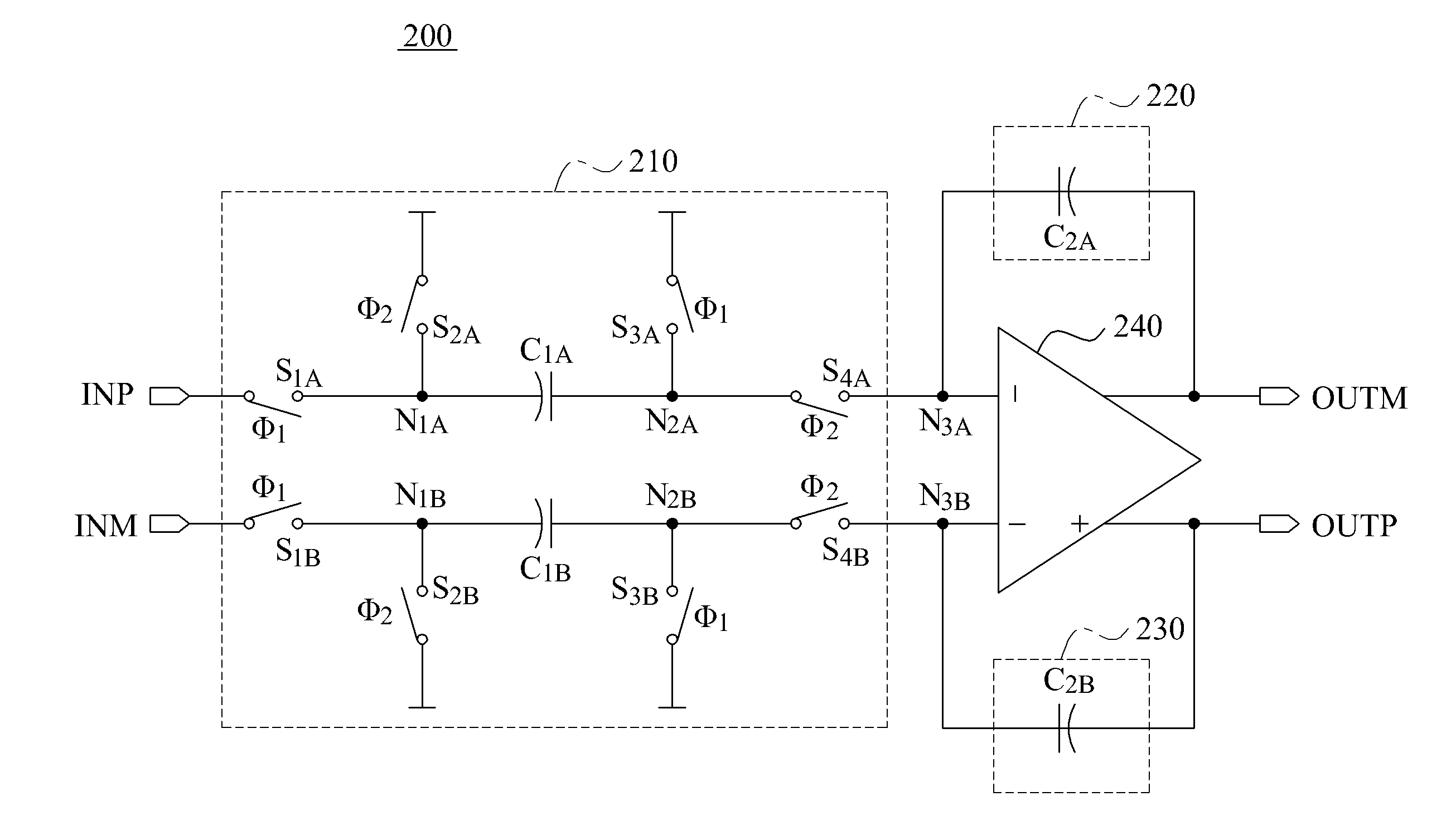
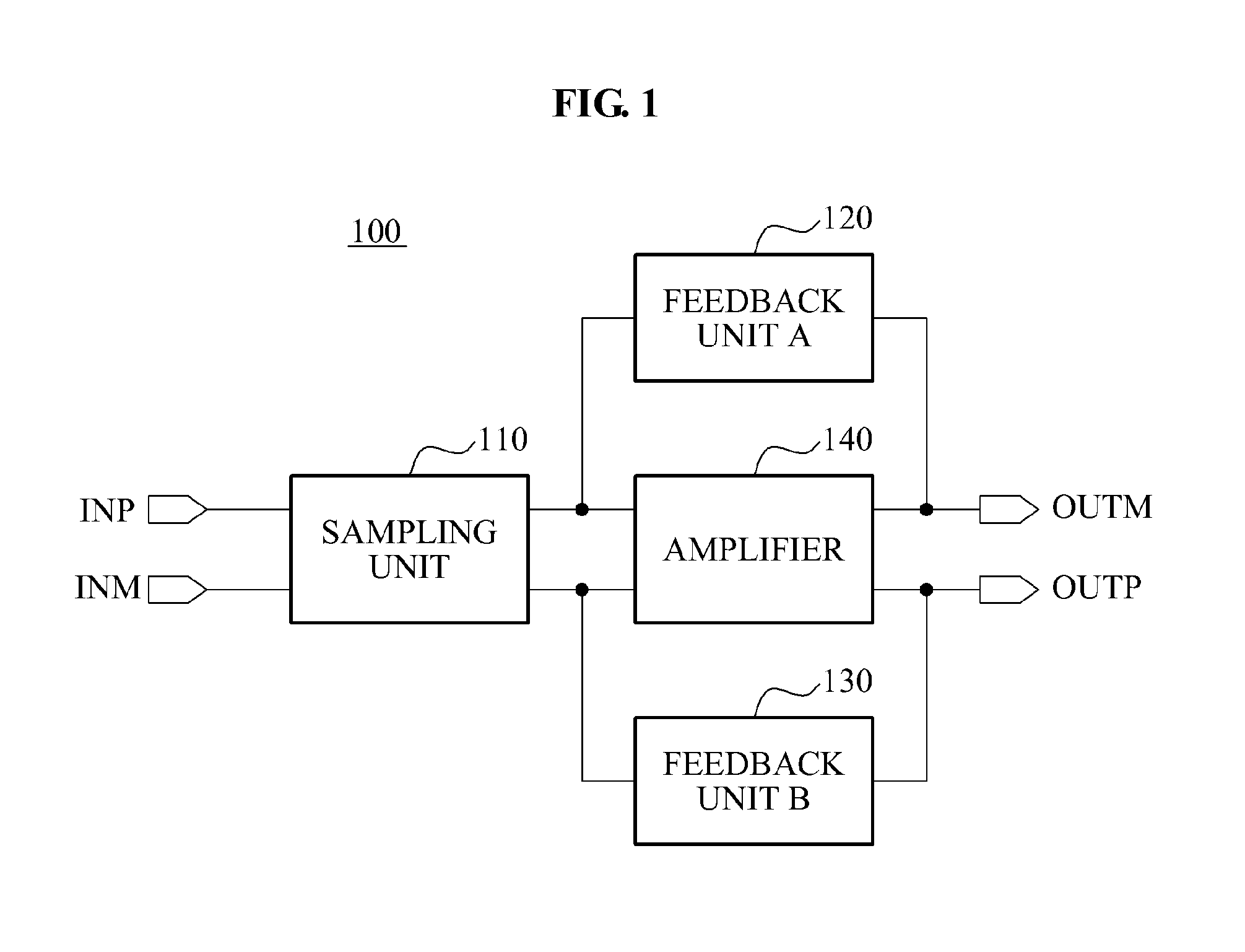
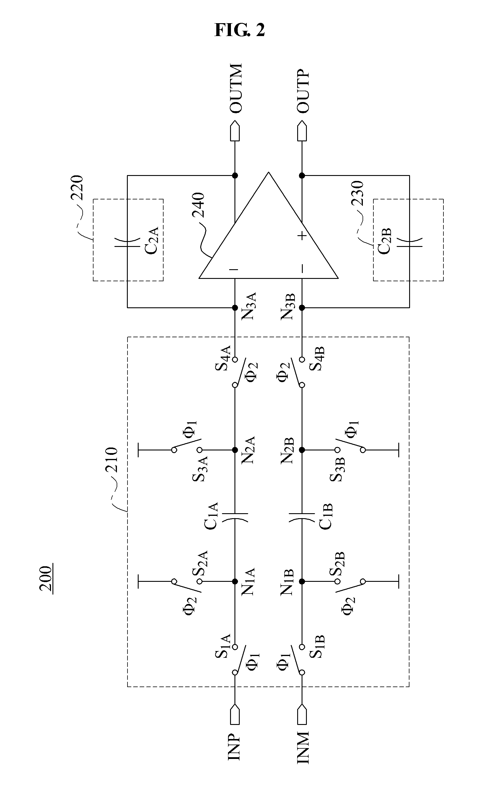
[0028]FIG. 1 is a block diagram illustrating a switched capacitor circuit 100 according to an embodiment of the present invention. Referring to FIG. 1, the switched capacitor circuit 100 may include a sampling unit 110, feedback units 120 and 130, and an amplifier 140.

[0029]The switched capacitor circuit 100 may perform a function of an integrator or an adder, through a sampling mode and an integration mode. An input voltage may be charged to the sampling unit 110 in the sampling mode. When the sampling unit 110 is completely charged, the input voltage may be referred to as being sampled to the sampling unit 110. An electric charge charged to the sampling unit 110...


PUM


Abstract

According to the present invention, a switched capacitor circuit comprises: an inverting amplifier for removing the offset by using a chopper stabilization circuit; a sampling unit which is connected between an input terminal and the inverting amplifier; and a feedback unit which is connected to the inverting amplifier in parallel.

Description

TECHNICAL FIELD[0001]The present invention relates to a semiconductor circuit, and more particularly, to a switched capacitor circuit.BACKGROUND ART[0002]In a semiconductor circuit, a switched capacitor circuit is widely used to improve a degree of integration and design a low power circuit. Performance of the switched capacitor circuit is being improved rapidly, along with a development of a complementary metal-oxide-semiconductor (CMOS) analog circuit technology.[0003]The switched capacitor circuit is used for various analog circuits, for example, an integrator, an adder, an analog filter, an analog-to-digital converter (ADC), a digital-to-analog converter (DAC), and the like. An operational amplifier (OP-Amp.) is typically used as one of main blocks of the switched capacitor circuit. However, the OP-Amp. has issues in terms of high power consumption and occupying a large area. Accordingly, use of an inverting amplifier using a relatively lower amount of power in the switched capa...

Claims


Application Information

Patent Timeline
Patent Type & Authority Applications(United States)
IPC IPC(8): H03F3/45
CPCH03F3/211H03F3/45475H03F3/45928H03F2203/45512H03F2203/45514H03F3/005H03F2203/45631H03F2203/45644H03F2203/45724H03F2203/45726H03H19/004H03F2203/45534H03F3/70H03H19/00
Inventor HAN, GUNHEECHAE, YOUNGCHEOLLEE, INHEELEE, DONGMYUNGLIM, SEUNGHYUNCHEON, JI MIN
Owner IND ACADEMIC CORP FOUND YONSEI UNIV
Why Eureka
Try Eureka