
Hydrogel Arthroplasty Device

a technology of arthroplasty and hydrogel, which is applied in the direction of femoral heads, prostheses, ligaments, etc., to achieve the effect of stimulating bone cell growth and/or adhesion

Active Publication Date: 2012-09-13
THE BOARD OF TRUSTEES OF THE LELAND STANFORD JUNIOR UNIV +1
View PDF13 Cites 28 Cited by
  • Summary
  • Abstract
  • Description
  • Claims
  • Application Information

AI Technical Summary

Benefits of technology

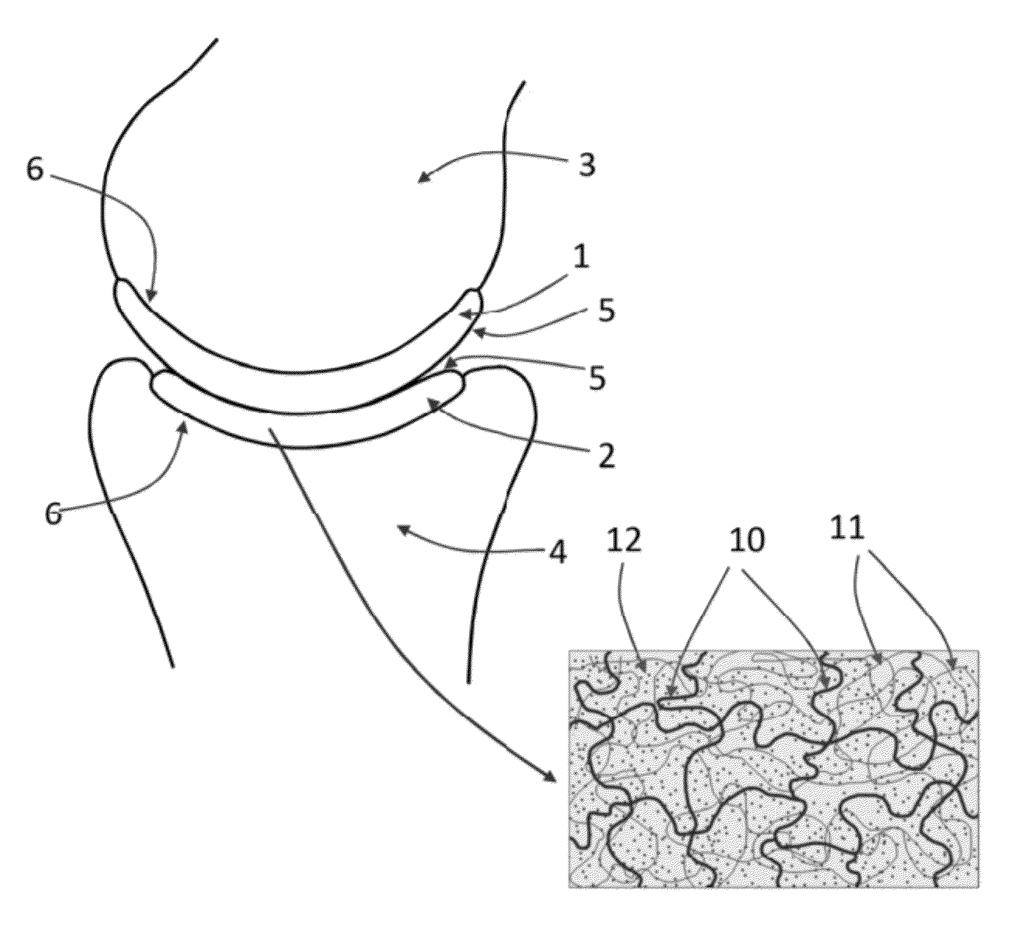
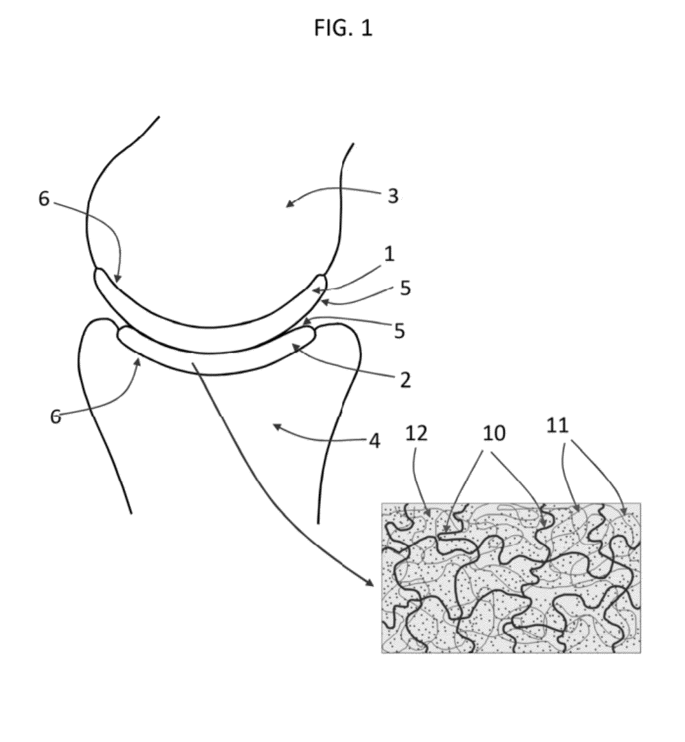
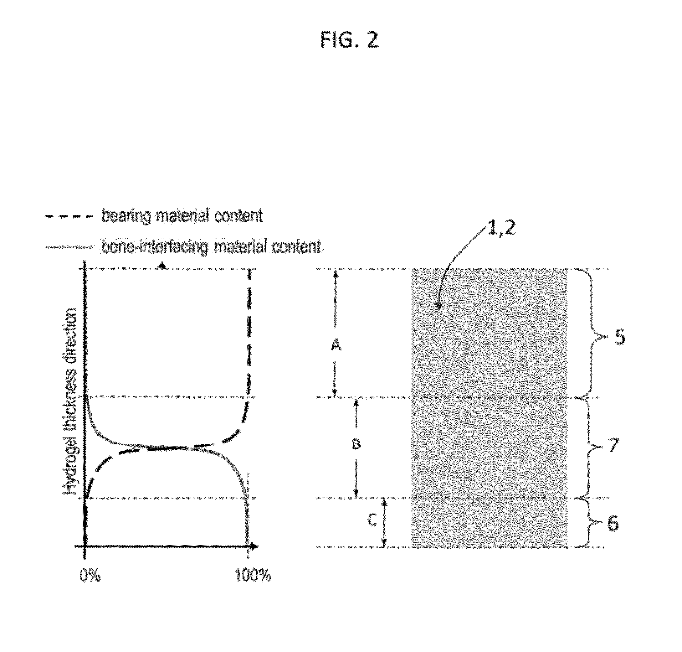
The present invention provides a bone-sparing arthroplasty device that can be used to replace damaged cartilage in joints. The device is made of a flexible, implantable hydrogel that can be shaped and sized to fit different joint surfaces. The hydrogel is designed to mimic the structure and function of natural cartilage, including its elastic modulus, fracture strength, and lubricious surface. The device can be used in a variety of joints, such as the hip, shoulder, and fingers. It is designed to protect the bone marrow interface and can be used in a cap-on-cap or cap-on-cartilage articulation. The device is made by a process called interpenetrating polymer network hydrogel strain-hardening, which involves swelling and a chemical cross-linking process. The resulting device has an increased stiffness and can be used in a bone-interfacing region to bind to the bone marrow interface. The device can also be combined with other arthroplasty devices or biomolecules to enhance its performance.

Problems solved by technology

However, if only one of the surfaces is damaged, then only one side can be capped, creating a cap-on-cartilage articulation.

Method used


Image

  • Hydrogel Arthroplasty Device
  • Hydrogel Arthroplasty Device
  • Hydrogel Arthroplasty Device

Examples


examples

[0093]The following description refers to an exemplary embodiment of a strain-hardened interpenetrating polymer network hydrogel with PEG as a first network 10 polymer and PAA as a second network 11 polymer. The IPN hydrogel is synthesized by a (two-step) sequential network formation technique based on UV initiated free radical polymerization. A precursor solution for the first network is made of purified, telechelic PEG dissolved at a typical concentration of 50% w / v in phosphate buffered saline (PBS) solution, water, or an organic solvent with either 2-hydroxy-2-methyl-propiophenone or 2-hydroxy-1-[4-(2-hydroxyethoxy)phenyl]-2-methyl-1-propanone as the UV sensitive free radical initiator. The types of telechelic PEG macromonomers used were PEG-diacrylate, PEG-dimethacrylate, PEG-diacrylamide, and PEG-diallyl ether. In other embodiments, either network can be synthesized by free radical polymerization initiated by other means, such as thermal-initiation and other chemistries not in...


PUM

PropertyMeasurementUnit
surface roughnessaaaaaaaaaa
molecular weightaaaaaaaaaa

Abstract

An arthroplasty device is provided having an interpenetrating polymer network (IPN) hydrogel that is strain-hardened by swelling and adapted to be held in place in a joint by conforming to a bone geometry. The strain-hardened IPN hydrogel is based on two different networks: (1) a non-silicone network of preformed hydrophilic non-ionic telechelic macromonomers chemically cross-linked by polymerization of its end-groups, and (2) a non-silicone network of ionizable monomers. The second network was polymerized and chemically cross-linked in the presence of the first network and has formed physical cross-links with the first network. Within the IPN, the degree of chemical cross-linking in the second network is less than in the first network. An aqueous salt solution (neutral pH) is used to ionize and swell the second network. The swelling of the second network is constrained by the first network resulting in an increase in effective physical cross-links within the IPN.

Description

CROSS REFERENCE TO RELATED APPLICATIONS[0001]This application is a continuation of U.S. patent application Ser. No. 12 / 148,534, filed Apr. 17, 2008, which claims the benefit of U.S. Provisional Patent Application 60 / 923,988, filed Apr. 17, 2007, and is a continuation-in part of pending U.S. patent application Ser. No. 12 / 070,336, filed Feb. 15, 2008, the disclosures of all of which are incorporated herein by reference; U.S. patent application Ser. No. 12 / 070,336 claims priority from U.S. Provisional Application No. 60 / 901,805, filed on Feb. 16, 2007, and is a continuation-in part of U.S. patent application Ser. No. 11 / 243,952, filed Oct. 4, 2005, now U.S. Pat. No. 7,857,849, which claims the benefit of U.S. Provisional Applications 60 / 616,262 filed on Oct. 5, 2004 and 60 / 673,172 filed on Apr. 20, 2005; U.S. patent application Ser. No. 12 / 070,336 is also a continuation-in-part of U.S. application Ser. No. 11 / 636,114, filed Dec. 7, 2006, now U.S. Pat. No. 7,857,447, which claims the b...

Claims


Application Information

Patent Timeline
Patent Type & Authority Applications(United States)
IPC IPC(8): A61F2/02
CPCA61F2/30756A61L2430/24A61F2/3603A61F2/3872A61F2/4202A61F2/4225A61F2/4241A61F2/4405A61F2002/30075A61F2002/30448A61F2002/30754A61F2002/3619A61F2210/0061A61F2220/005A61F2310/00293A61L27/3843A61L27/52A61F2/34A61F2002/30593A61F2/36A61L27/18A61L27/34A61L27/50
Inventor MYUNG, DAVIDKOURTIS, LAMPROSHARTMANN, LAURAFRANK, CURTIS W.GOODMAN, STUART B.CARTER, DENNIS R.
Owner THE BOARD OF TRUSTEES OF THE LELAND STANFORD JUNIOR UNIV
Learn More