Non-contact power transmission system, receiving apparatus and transmitting apparatus

a power transmission system and non-contact technology, applied in the direction of near-field systems using receivers, instruments, transportation and packaging, etc., can solve the problems of shortening the transmission distance, difficult to reduce the size of portable terminal devices, and restricting the position of mounting, so as to reduce the fluctuation of frequency characteristics, the effect of superior transmission efficiency and superior efficiency

Active Publication Date: 2012-09-20
MAXELL HLDG LTD
View PDF2 Cites 131 Cited by
  • Summary
  • Abstract
  • Description
  • Claims
  • Application Information

AI Technical Summary

Benefits of technology

[0029]With applying such configuration, since the resonating frequency of the resonance coil at the power transmitter side is equal to that of the resonance coil at the power receiver side, the magnetic flux generated by current flowing through the resonance coil at the power transmitter side and the magnetic flux generated by current flowing through the resonance coil at the power receiver side are same in the phases thereof; therefore, those resonance coils are coupled with, strongly, therebetween. This phenomenon is called, the magnetic resonance phenomenon, and since this has characteristics that the decrease of the efficiency is less than that of the electromagnetic induction method, which is mainly applied in the conventional non-contact transmission, even if the coils are separated in the distance therebetween, then the decrease of the transmission efficiency is less when the power transmitting apparatus and the power receiving apparatus are separated in the distance therebetween, in a certain degree, therefore it is possible to achieve the structure having less restriction of the position where a power receiving antenna is mounted, in particular, when mounting the power receiving apparatus on the portable terminal device.
[0039]With applying such configuration mentioned above, since there is obtained a result that the fluctuation of the frequency characteristics comes to be small between the primary coil and the secondary coil due to the fluctuation of the distance between the coils of the magnetic resonance coil (i.e., the impedance fluctuation comes to be small of the input due to fluctuation of the distance between the coils), through the experiment, it is possible to suppress the fluctuation of the frequency characteristics between the primary coil and the secondary coil due to the fluctuation of the distance between the coils, without using a variable impedance circuit, and therefore also the transmitter circuit can be made small in the size thereof.
[0040]Further, as a means for making the fluctuation of the frequency characteristics between the primary coil and the secondary coil due to the fluctuation of the distance between the coils of the magnetic resonance coil, plural numbers of resonance coils are provided on a side of the primary coil, and the number of turns thereof is determined so that the respective coil shows the most superior transmission efficiency corresponding to the distance between the load coil, and then, since it is possible to make transmission, mainly, between the resonance coil, which is most superior in the efficiency, corresponding to the distance between the resonance coil on the primary side and the load coil, i.e., it is possible to reduce the fluctuation of the frequency characteristics between the primary coil and the secondary coil due to the fluctuation of the distance between the coils, even by the means mentioned above.
[0041]Also, for dissolving the problem that the transmission efficiency is lowered at very close distance between the coils of the magnetic resonance coil, such as, several mm, the power supply coil and the magnetic resonance coil on the primary side are replace with each other in the positions thereof, so that the distance between the power supply coil and the load coil is nearer than that between the resonance coil and the load coil at the primary side. With this, it is possible to suppress deterioration of the transmission efficiency in the case of the magnetic resonance at the distance of around several mm between the primary coil and the secondary coil, and also lowering of the transmission efficiency even in the case of the transmission of very close distance. This is because the electric power can be transmitted from the power supply coil to the load coil, directly, through the electromagnetic induction, since the power supply coil and the load coil come to close each other in the distance thereof, at the very close distance.
[0042]Further, in the non-contact power transmission system, as a communication means for conducting the authentication of the equipment for confirming if it is enabled with the non-contact power charging or not, and / or the control of an amount of electric power to be transmitted, etc., a modulation, such as, ASK (Amplitude Shift Keying) modulation, etc., is treated on the signal at the transmitter side, and at the same time in the structure at the receiver side, there is applied a load modulation method for enabling the communication with using the signal received even if not having the electric power in an inside thereof; thereby obtaining the non-contact power transmission system for enabling the communication relatively in ease.
[0043]According to the present invention, it is possible to obtain the non-contact power transmission system, the power receiving apparatus and the power transmitting apparatus, for enabling to withhold the terminal device from becoming large in sizes thereof due to mounting of those, i.e., if mounting the non-contact communication means and the non-contact power receiving apparatus for charging up the battery on the terminal device, and having less transmission loss between the antennas, and less influence on the communication sensitivity of the portable terminal device if the transmission distance becomes large, when conducting the non-contact communication and the non-contact power receiving, by applying the magnetic resonance method therein.

Problems solved by technology

For this reason, when trying to mount such charging system, as shown in FIG. 24, on the portable terminal, upon which a demand of small-sizing is high, in particular, it is necessary to build up two (2) sets of the coil-like antennas mentioned above therein, i.e., has a problem that it is difficult to reduce size of the portable terminal devices.
Further, with the charging system of the conventional technology shown in FIG. 24 mentioned above, in power transmission thereof, since an efficiency of the transmitting apparatus is lowered and power consumption increases if a transmission loss is large at a non-contact portion thereof, it is common to apply an electromagnetic induction method, with which a relatively high efficiency at a short distance (equal or less than several millimeters); however, on the contrary, if the transmission distance is large to a certain extent (for example, 1 to 2 cm, approximately), since the transmission efficiency is deteriorated abruptly, it is necessary to shorten the transmission distance between the transmitting apparatus and the receiving apparatus when charging, in particular, if trying to mount the receiving apparatus on the portable terminal device, such as, by applying an antenna for the receiving apparatus on a surface of the portable terminal device, etc., then there is a problem that a position for mounting is restricted.
For this reason, reflection occurs on the antenna portion for conducting non-contact communication and the non-contact power transmission, and then it has a problem of giving ill influences on a receiving sensitivity of the portable terminal device.
For this reason, there is necessity of applying a mechanical variable capacity, such as, a variable capacitor, etc., for example, it is impossible to achieve small-sizing of the transmitter.
There is also a problem of insurability because the variable capacitor is a mechanical one.

Method used


Image

  • Non-contact power transmission system, receiving apparatus and transmitting apparatus
  • Non-contact power transmission system, receiving apparatus and transmitting apparatus
  • Non-contact power transmission system, receiving apparatus and transmitting apparatus

Examples


embodiment 1

[0073]Explanation will be given on a first embodiment of a non-contact power charging system, according to the present invention, by referring to drawings attached herewith.

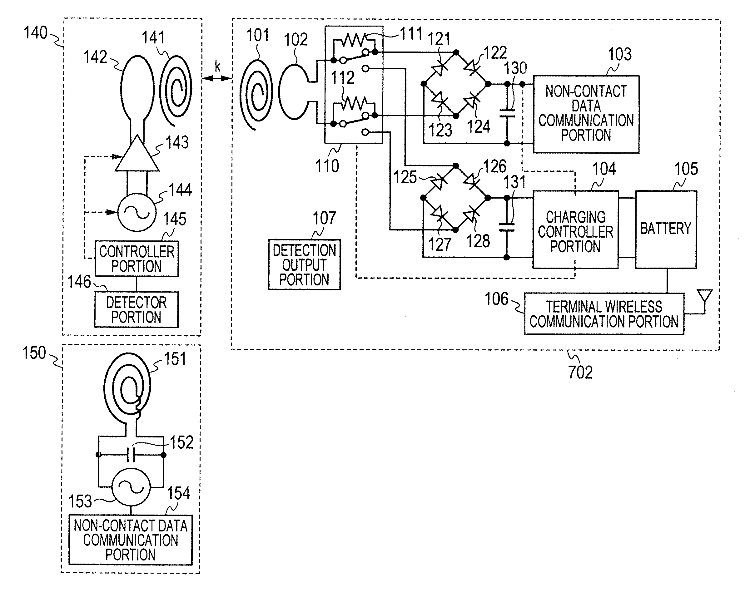
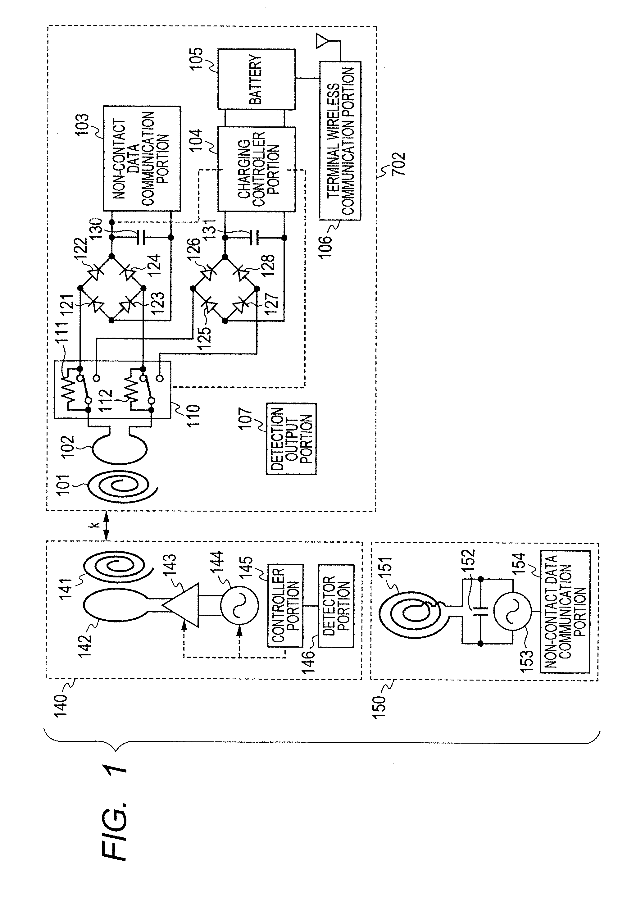
[0074]FIG. 1 is a view for showing the first embodiment having the non-contact power charging system to be applied in the present invention.

[0075]In the figure, a reference numeral 702 depicts a mobile or portable terminal device, 140 a transmitting apparatus for conducting non-contact transmission of electric power, 150 a non-contact communicating apparatus, wherein the portable terminal device 702 shown in the figure comprises a magnetic resonance coil 101, a load coil 102, an changeover switch 110, rectifying diodes 121, 122, 123, 124, 125, 126, 127 and 128, smoothing capacitors 130 and 131, a non-contact data communication portion 103, a charging controller portion 104, a battery 105, a terminal wireless communication portion 106, and a detection output portion 107, and further damping or attenuating resistor...

embodiment 2

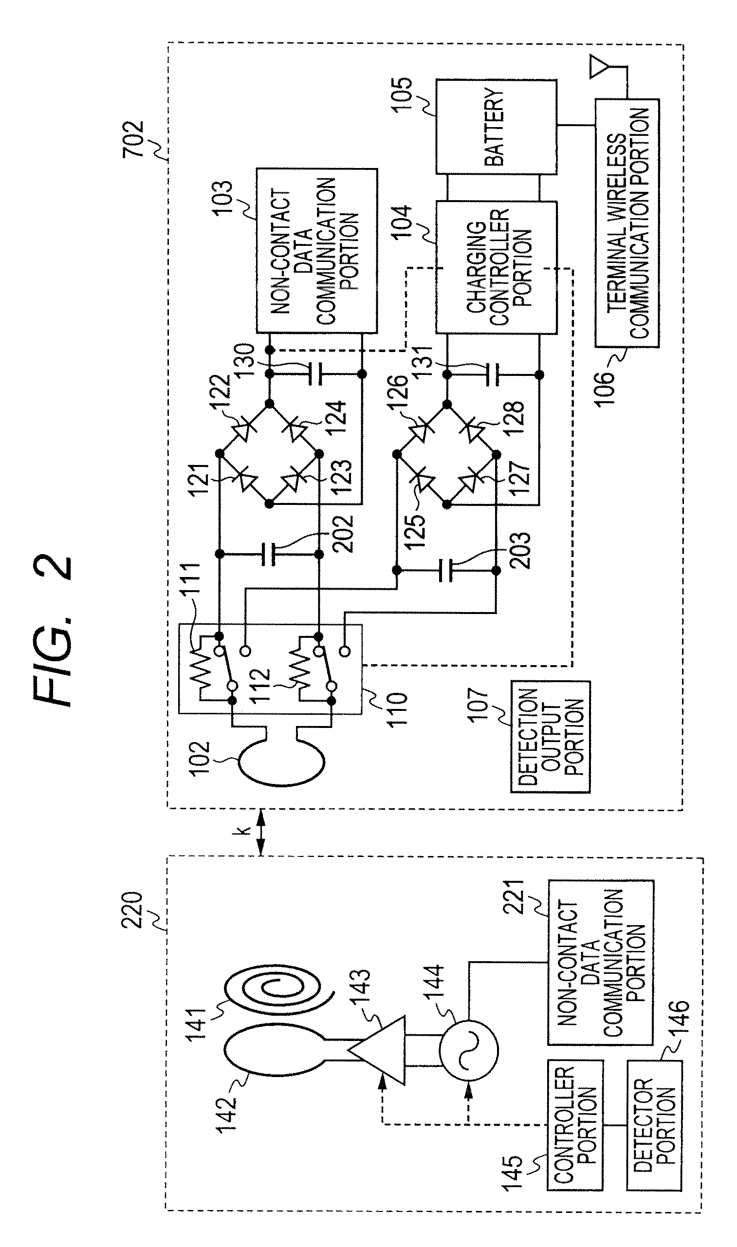
[0089]FIG. 2 is a view for showing a second embodiment of the non-contact power charging system, to be applied in the present invention.

[0090]The figure shows that applying a coil of the electromagnetic induction method in the portable terminal device 702 while a coil of the magnetic resonance method in a power transmitting apparatus 220, comparing to the first embodiment shown in FIG. 1. However, in the figure, although there is applied the power transmitting apparatus 220 unifying the communication apparatus and the power transmitting apparatus in one body, but the present invention should not be limited to this. As was shown in FIG. 1, the coil of the electromagnetic induction method may be applied to the portable terminal device while applying the coil of the magnetic resonance method to the power transmitting apparatus, even in case where the communication apparatus and the power transmitting apparatus are separated from each other.

[0091]In the figure, a reference numeral 201 d...

embodiment 3

[0100]FIG. 3 is a view for showing a third embodiment of the non-contact power charging system, to be applied in the present invention.

[0101]In the figure, a reference numeral 301 depicts a resonance capacitor, 310 a changeover switch, 311 an attenuation resistor, 312, 313, 314 and 315 rectifying diodes, which are used in common with in the non-contact communication and the non-contact power transmission, but others corresponding to those shown in FIG. 2 are attached with the same reference numerals, and the explanations thereof will be omitted herein.

[0102]In the power transmitting apparatus 220, when conducting the non-contact communication between the portable terminal device 702, the non-contact data communication portion 221 modulates the oscillation signal of the oscillator 144 in accordance with the communication data, and the signal modulated is amplified by the amplifying portion 143, to be transmitted through a power transmission antenna, which is constructed with the powe...


PUM


Abstract

A non-contact power transmission system comprises: a primary coil including a power supply coil and a magnetic resonance coil; and a secondary coil including a load coil, thereby transmitting an electric power from the power supply coil at a self-resonating frequency of the magnetic resonance coil, which is determined by a parasitic capacitance between wound wires of the coil and a self inductance of the coil, and taking out the electric power supplied, from the load coil of the secondary coil through magnetic coupling, with non-contact, wherein the electric power is transmitted, with non-contact, with applying magnetic coupling in coupling between the power supply coil and the magnetic resonance coil and coupling between the magnetic resonance coil and the load coil.

Description

[0001]This application relates to and claims priority from Japanese Patent Application No. 2011-057375 filed on Mar. 16, 2011, the entire disclosure of which is incorporated herein by reference.BACKGROUND OF THE INVENTION[0002]The present invention relates to a non-contact (or contact-less) data communication means and a non-contact power transmitting means applying a magnetic resonance therein, and an apparatus and an antenna for transmitting between those, and it relates to an effective technology to be applied to an apparatus for charging mobile equipments, which mount a non-contact IC card and / or a battery therein, in contactless (inductively).[0003]As the technology, upon which the inventors of the present invention studied, in relation to the conventional technology of the non-contact power charging system, there can be considered one having such structure as shown in FIG. 24, as one example thereof, for example.[0004]FIG. 24 is a block diagram for showing one example of the c...

Claims


Application Information

Patent Timeline
Patent Type & Authority Applications(United States)
IPC IPC(8): H02J17/00H02J7/00G06K17/00G06K19/07H04B5/02
CPCH02J7/0021H02J2007/0001H02J17/00H04B5/0025H04B5/0031H04B5/0037H04B5/0075H04B5/0081H04B5/0087H04B5/0093H02J50/12H02J50/80H02J7/00045H02J50/402H02J7/0047Y02T10/70
Inventor ICHIKAWA, KATSUEI
Owner MAXELL HLDG LTD
Why Eureka
Try Eureka