[0006]The present invention can more suitably set a difference in pressure between an engagement side oil chamber defined on one side of a piston that configures a clutch, and a back-pressure side oil chamber defined on the other side of the piston, without making a control more complex.
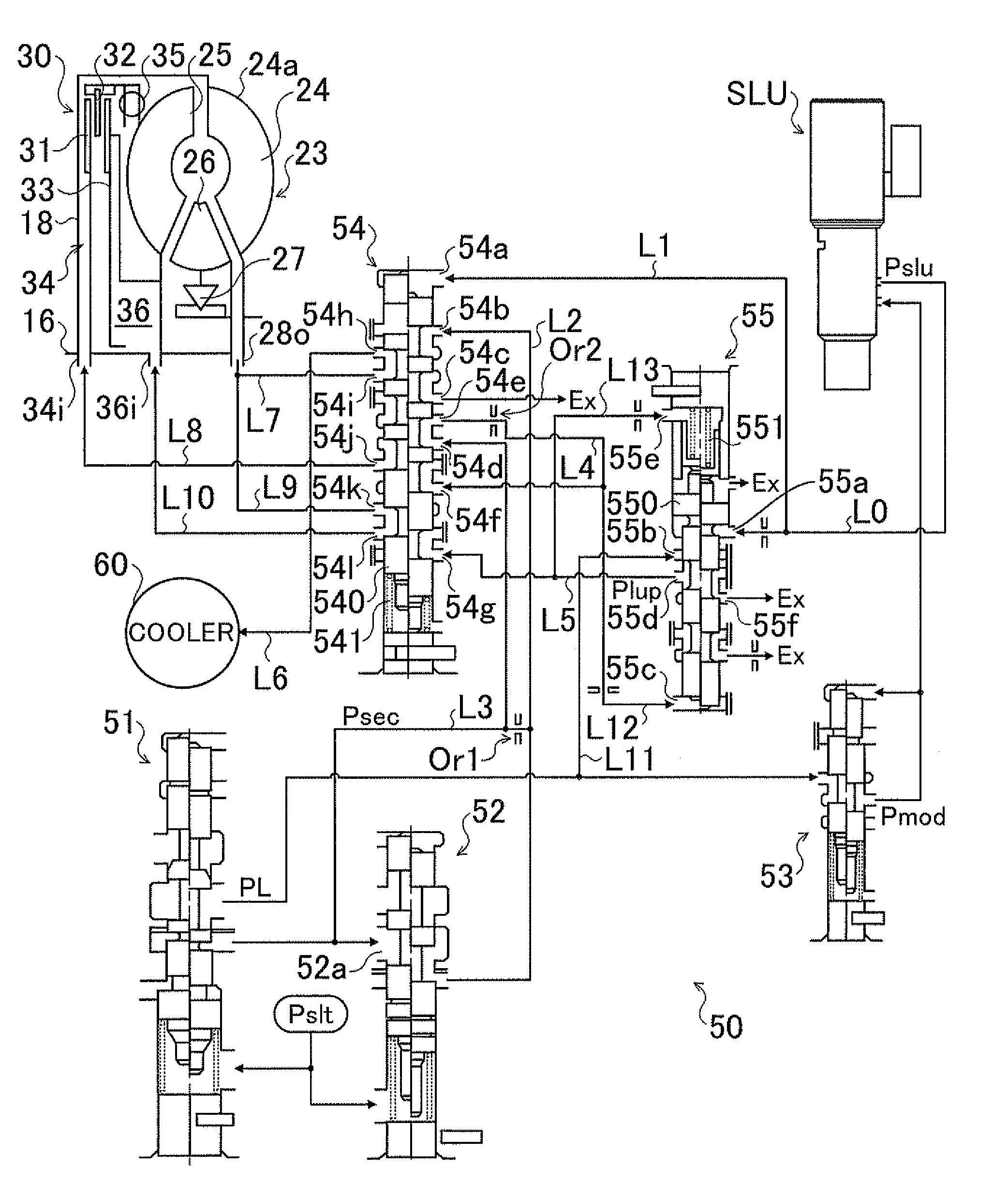
[0009]The hydraulic control device includes the secondary pressure generating valve that generates the secondary pressure by adjusting the pressure of hydraulic oil drained from the line pressure generating valve so as to be lower than the line pressure; and the clutch engagement pressure generating valve that generates the clutch engagement pressure by adjusting the line pressure from the line pressure generating valve. To engage the hydraulic clutch, the clutch engagement pressure from the clutch engagement pressure generating valve is supplied to the engagement side oil chamber, and the secondary pressure from the secondary pressure generating valve is supplied to the back-pressure side oil chamber. Thus, the hydraulic pressure within the back-pressure side oil chamber and the engagement side oil chamber, i.e., the difference in pressure between the back-pressure side oil chamber and the engagement side oil chamber, can be suitably set based on the engagement state (e.g., fully engaged or slip-controlled state) of the hydraulic clutch without making the control of the secondary pressure generating valve and the clutch engagement pressure generating control valve more complex.
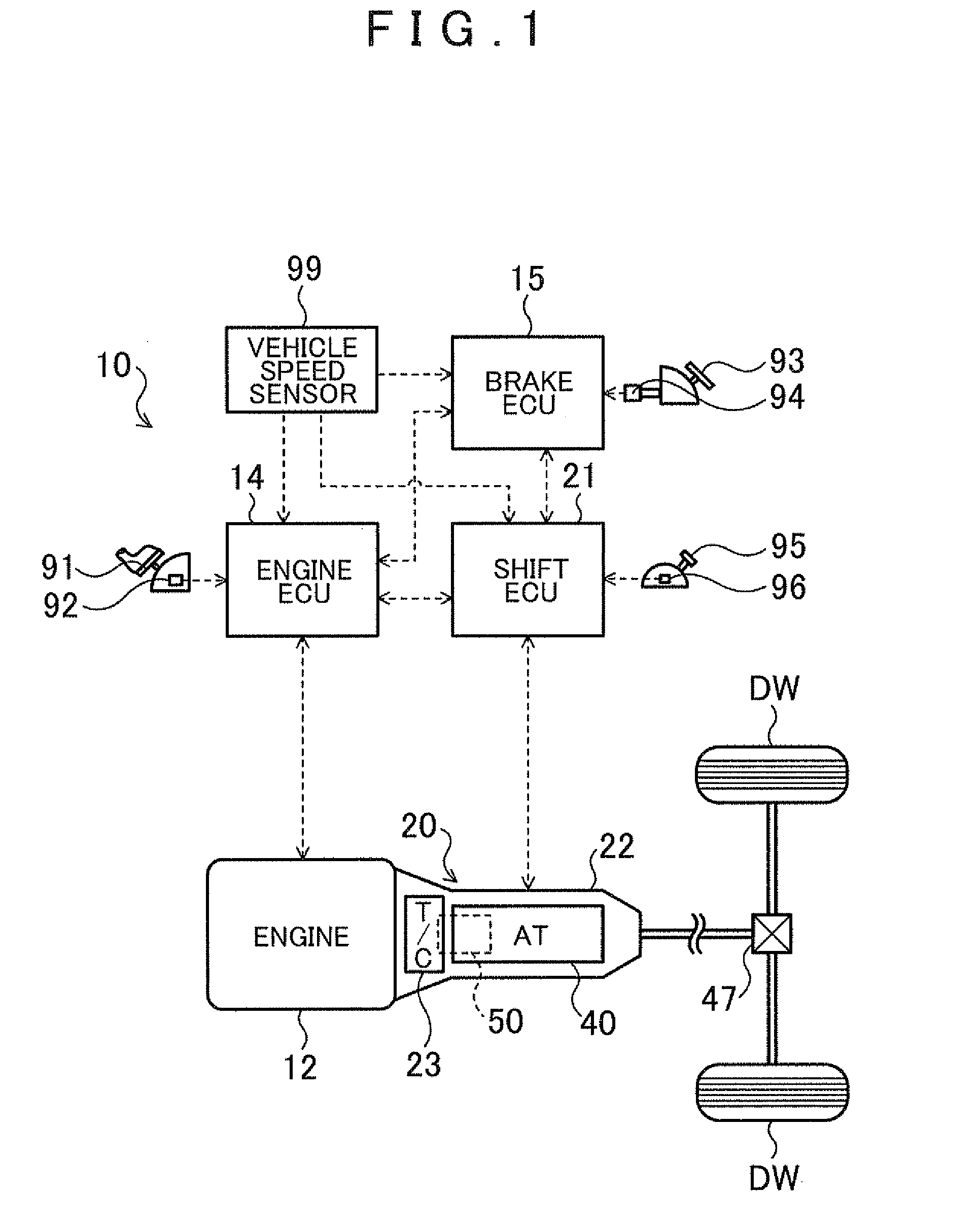
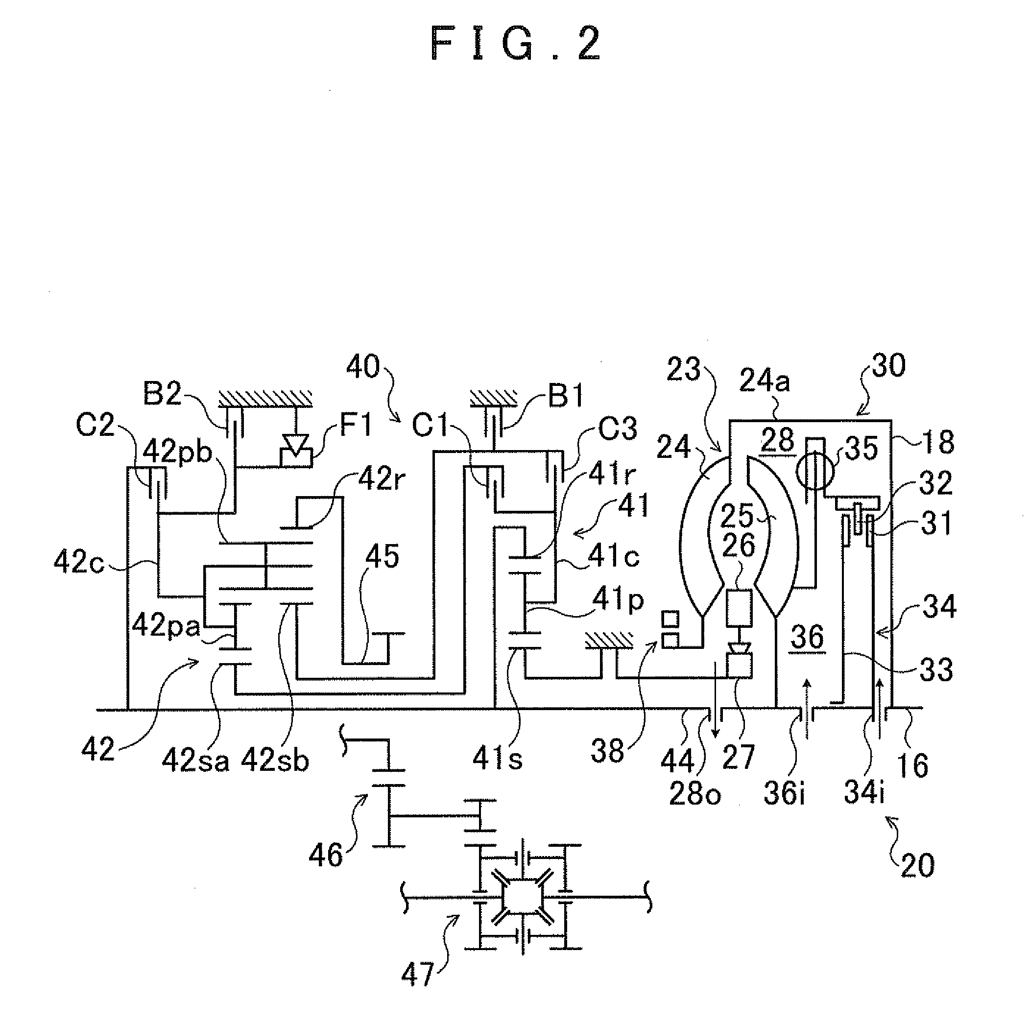
[0010]The hydraulic clutch may be a lock-up clutch that directly couples an input member connected to a motor and an input shaft of a transmission in a locked-up state and cancels the locked-up state, and the back-pressure side oil chamber may communicate with a fluid transmission chamber in which power is transmitted through hydraulic oil between an input-side fluid transmission element and an output-side fluid transmission element that configure a fluid transmission device. If the hydraulic control device is applied to the above configuration, a sufficient amount of hydraulic oil is supplied from the secondary pressure generating valve to the fluid transmission chamber through the back-pressure side oil chamber, and it is possible to suppress the occurrence of
cavitation when there is a large difference between the rotation speeds of the input-side fluid transmission element and the output-side fluid transmission element. By increasing (raising) a source pressure of the clutch engagement pressure faster than the secondary pressure, it is possible to well secure a difference in pressure between the clutch engagement pressure supplied to the engagement side oil chamber and the secondary pressure supplied to the back-pressure side oil chamber even if the rotation speed of the motor is low. Therefore, it is possible to set the lock-up clutch to a fully engaged or slip-controlled state even while the rotation speed of the motor is low.
[0011]The line pressure generating valve may generate the line pressure by adjusting the hydraulic pressure from the
oil pump in accordance with a control pressure that is set based on a drive power request for the motor, and the secondary pressure generating valve may generate the secondary pressure by adjusting the pressure of hydraulic oil drained from the line pressure generating valve so as to be lower than the line pressure based on the control pressure. Accordingly, when the drive power request (torque request) for the motor is large, the secondary pressure to be supplied to the back-pressure side oil chamber can be increased in accordance with the drive power request so that a sufficient amount of oil within the back-pressure side oil chamber and the fluid transmission chamber can be ensured. In addition, the line pressure serving as the source pressure of the clutch engagement pressure can also be increased in accordance with the drive power request at such time. Therefore, the difference in pressure between the engagement side oil chamber and the back-pressure side oil chamber can be suitably set even if the secondary pressure supplied to the back-pressure side oil chamber is increased. Thus, according to the above configuration, an increase in the size of the
oil pump can be suppressed and the generation of heat in the lock-up clutch (hydraulic clutch) can be suppressed. At the same time, it is also possible to lock up the lock-up clutch in a smooth manner when the rotation speed of the motor is low, as well as smoothly slip the lock-up clutch when the torque output from the motor is high, and expand the slip area of the lock-up clutch. When the drive power request is small, the secondary pressure to be supplied to the back-pressure side oil chamber can be decreased in accordance with the drive power request so that an increase in the amount of oil within the back-pressure side oil chamber and the fluid transmission chamber can be suppressed.
[0013]The oil passage connected to the pressure regulating port of the secondary pressure generating valve may include an oil amount restricting mechanism that adjusts an amount of hydraulic oil flowing out to the
lubrication target through the orifice. Thus, the amount of hydraulic oil flowing out to the
lubrication target through the orifice can be even better adjusted.
[0015]The lock-up clutch may be a multi-plate clutch. That is, according to the present invention, the difference in pressure between the engagement side oil chamber and the back-pressure side oil chamber of the multi-plate clutch that is relatively more susceptible to generating heat can be more suitably set.

