Light source apparatus and image display apparatus using the same

a technology of light source and image display, which is applied in the field of light source equipment, can solve the problems of image quality deterioration, short life of light source, and short maintenance life of light source, and achieve the effect of high color purity and high brightness

Active Publication Date:
View PDF8 Cites 210 Cited by
  • Summary
  • Abstract
  • Description
  • Claims
  • Application Information

AI Technical Summary

Benefits of technology

[0015]The present invention is proposed in view of the actual circumstances described above, and it is an object of the present invention to provide a light source apparatus using phosph

Problems solved by technology

The use, however, of a high-pressure mercury lamp as a light source has a problem that mercury is contained, and also causes a problem that a short lifetime of the light source complicates the maintenance.
Due to its high coherence, however, the laser light causes speckle noise, which results in the deterioration of the image quality.
In particular, laser light in the green and yellow wavelength ranges, which has a high luminosity factor for human eye, has a major problem that the ima

Method used


Image

  • Light source apparatus and image display apparatus using the same
  • Light source apparatus and image display apparatus using the same
  • Light source apparatus and image display apparatus using the same

Examples


first embodiment

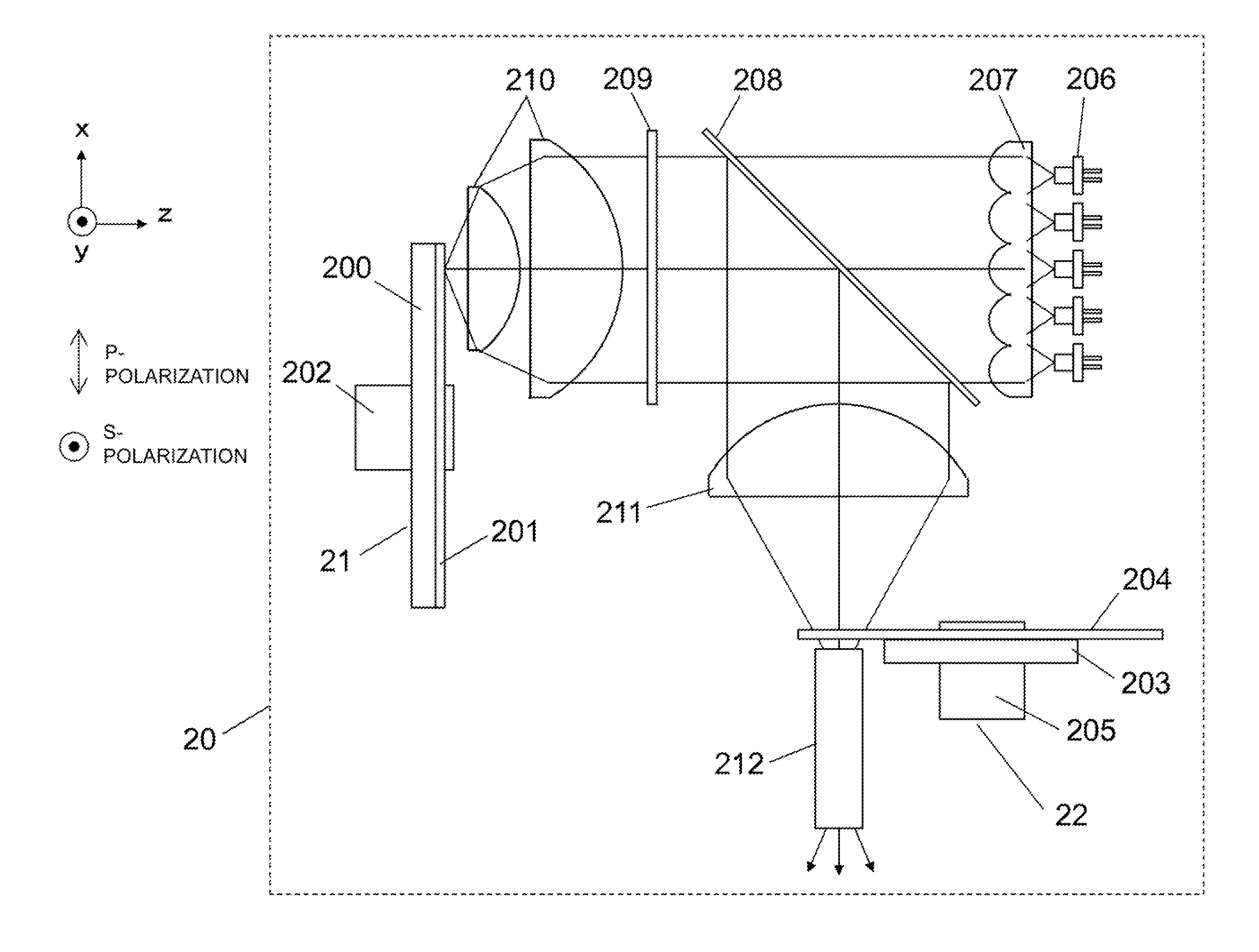
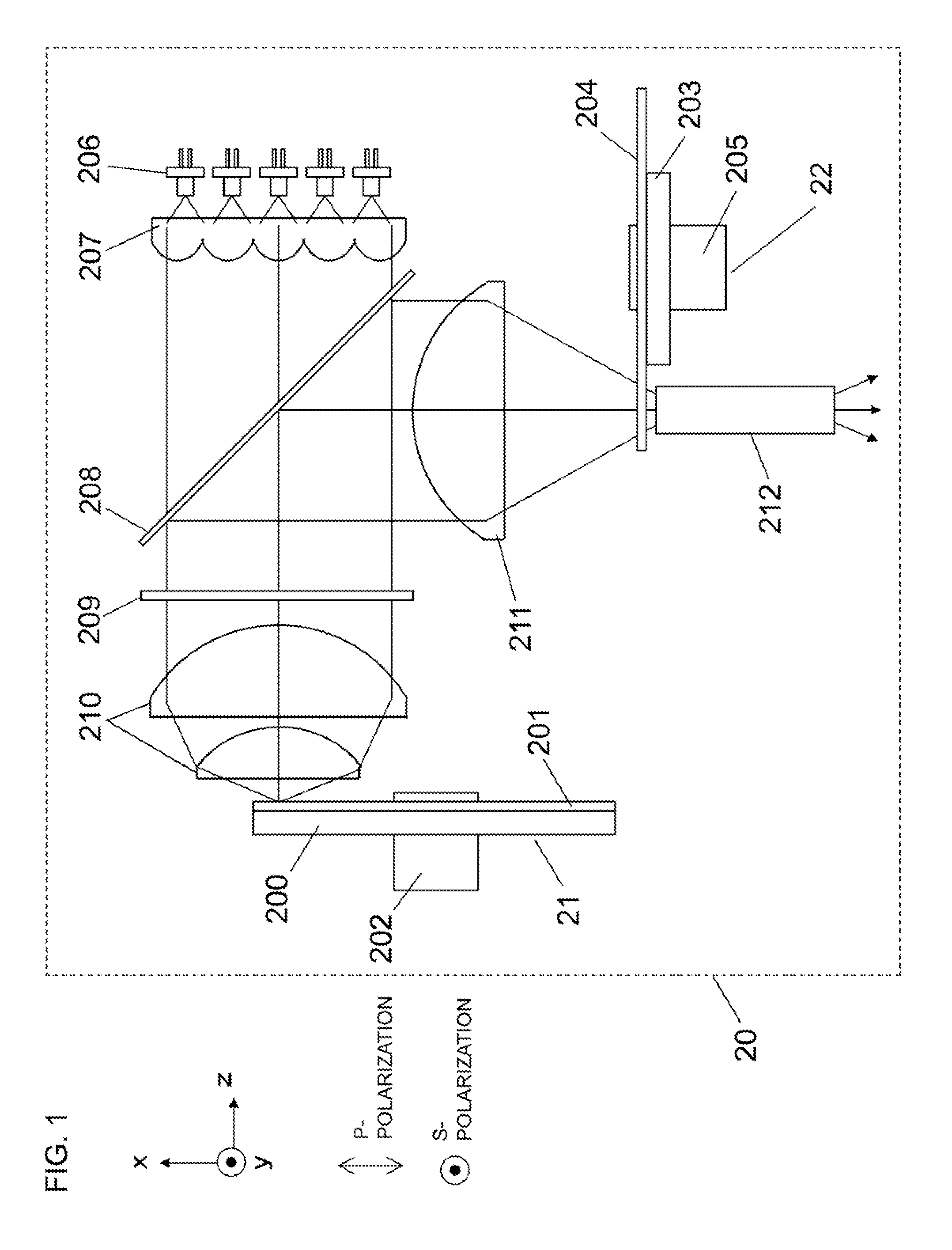
[0059]FIG. 1 shows the structure of a light source apparatus 20 according to a first embodiment of the present invention.

[0060]The light source apparatus 20 according to the first embodiment shown in FIG. 1 includes a first wheel 21, a second wheel 22, an excitation light source 206, a collimating lens array 207, a dichroic mirror 208, a quarter-wave plate 209, light collecting lenses 210 and 211, and a rod integrator 212. The light output from the light source apparatus 20 is formed of light that switches periodically among three time segments, namely red light, green light, and blue light, and the output light can be used as the illumination light of an image display apparatus or the like.

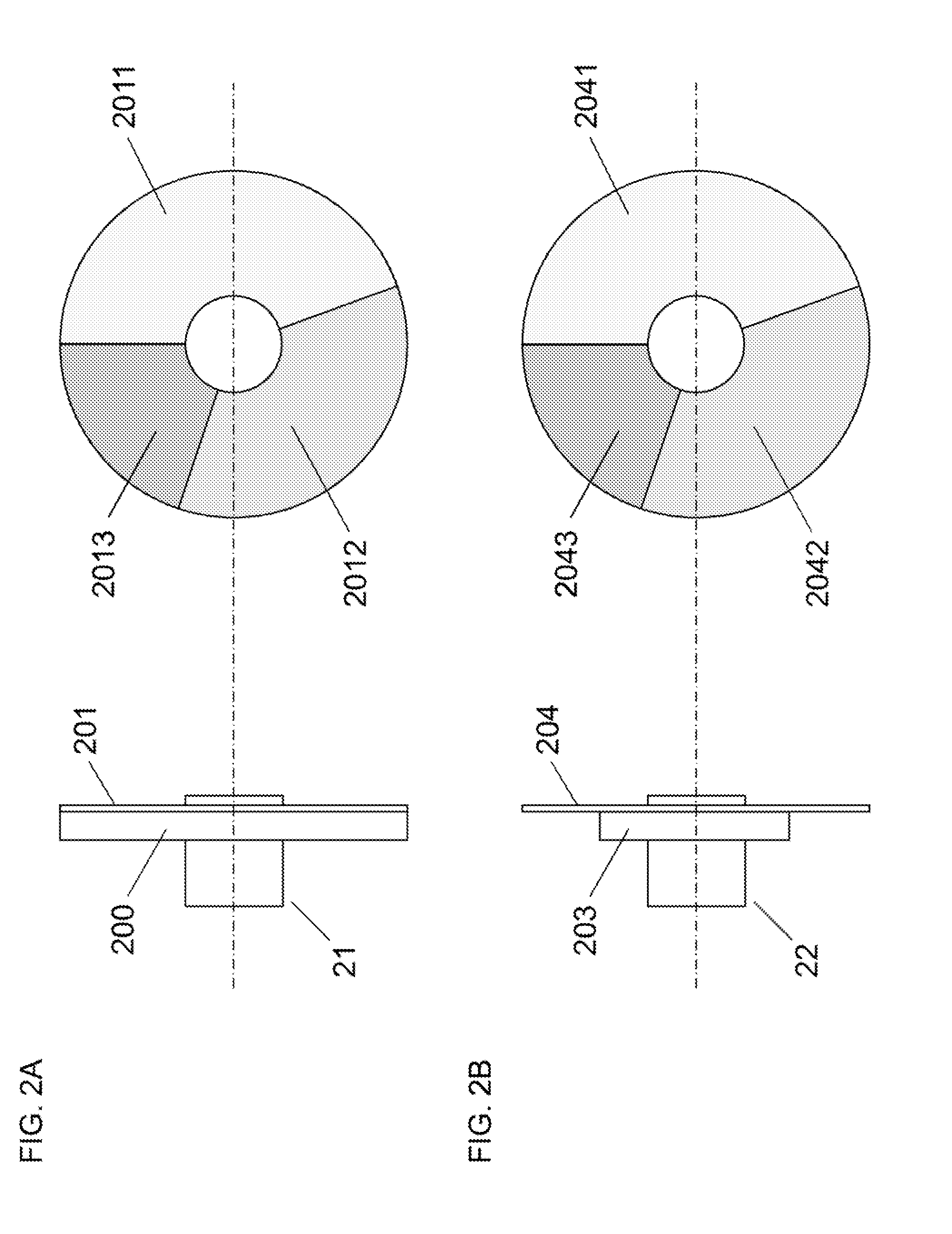
[0061]The first wheel 21 includes a substrate 200, a phosphor layer 201, and a rotation control section 202. The substrate 200 is a circular piece of parallel plate glass, and is coated with dichroic coating on the glass surface on one side thereof, the dichroic coating reflecting light in the en...

second embodiment

[0104]FIG. 5 shows the structure of a light source apparatus 30 according to a second embodiment of the present invention.

[0105]The light source apparatus 30 according to the second embodiment shown in FIG. 5 includes a first wheel 21, a second wheel 22, an excitation light source 306, a collimating lens array 207, a dichroic mirror 308, a quarter-wave plate 209, light collecting lenses 210 and 211, and a rod integrator 212. Similarly to the first embodiment, the light output from the light source apparatus 30 is formed of light that switches periodically among three time segments, namely red light, green light, and blue light, and the output light can be used as the illumination light of an image display apparatus or the like.

[0106]The light source apparatus 30 according to the second embodiment is different from the light source apparatus 20 according to the first embodiment described above in the excitation light source 306 and the dichroic mirror 308. Further, in accordance with...

third embodiment

[0112]FIG. 7 shows the structure of a light source apparatus 40 according to a third embodiment of the present invention.

[0113]The light source apparatus 40 according to the third embodiment shown in FIG. 7 includes a first wheel 41, a second wheel 22, excitation light sources 206 and 306, two collimating lens arrays 207, a polarized beam splitter 410, dichroic mirrors 411 and 416, a collimating lens 413, reflecting mirrors 414 and 415, light collecting lenses 210 and 211, and a rod integrator 212. Similarly to the first and second embodiments, the light output from the light source apparatus 40 is formed of light that switches periodically among three time segments, namely red light, green light, and blue light, and the output light can be used as the illumination light of an image display apparatus or the like.

[0114]The light source apparatus 40 according to the third embodiment is different from the light source apparatus 20 according to the first embodiment described above in th...


PUM


Abstract

A light source apparatus includes: an excitation light source including a laser light source; a first wheel that is controlled to rotate, and includes, in a part of a surface thereof to be illuminated by excitation light emitted from the excitation light source, a phosphor layer to be excited by the excitation light; a dichroic mirror that guides fluorescence emitted from the phosphor layer of the first wheel and the excitation light to an illumination optical system; and a second wheel that is controlled to rotate, and includes a dichroic filter that transmits light having a desired wavelength component of each of the fluorescence and the excitation light output from the dichroic mirror.

Description

BACKGROUND OF THE INVENTION[0001]1. Field of the Invention[0002]The present invention relates to a light source apparatus using a laser light source and phosphors, and in particular, relates to a light source apparatus that emits visible light such as red, green, and blue light, and also to an image display apparatus using the light source apparatus.[0003]2. Description of the Background Art[0004]Today, a projector is widely used as an image display apparatus that projects various video images and the like onto a screen in an enlarged manner. The projector causes a spatial light modulation device, such as a digital micromirror device (DMD) or a liquid crystal display device, to collect the light emitted from a light source, and causes the light modulated with an image signal and emitted from the spatial light modulation device, to be displayed as a color image on the screen.[0005]To obtain a bright large-screen video image in the projector, a high-pressure mercury lamp having a high...

Claims


Application Information

Patent Timeline
IPC IPC(8): H04N5/74F21V9/14F21V9/16
CPCH04N9/3111H04N5/7416G03B21/204G02B26/008H04N9/3114G03B33/12F21V9/00G03B21/2066F21S10/007F21V13/08F21V13/06G03B21/28G03B21/16G03B21/2073H04N9/3158F21K2/00F21V9/08H04N9/3161F21V9/20
Inventor KITANO, HIROSHI
Why Eureka
Try Eureka