Honeycomb filter

a technology of honeycomb filter and filter body, which is applied in the direction of filtration separation, separation process, transportation and packaging, etc., to achieve the effect of easy production, simplified configuration, and enhanced mechanical strength of honeycomb filter

Active Publication Date: 2012-09-27
NGK INSULATORS LTD
View PDF3 Cites 20 Cited by
  • Summary
  • Abstract
  • Description
  • Claims
  • Application Information

AI Technical Summary

Benefits of technology

[0008]The present invention has been accomplished under these circumstances. A main object of the present invention is to provide a honeycomb filter having an enhanced performance of trapping solid components contained in fluid.
[0017]A honeycomb filter according to the present invention may be loaded with a catalyst. In this case, for example, removal of trapped solid components by combustion can be more efficiently performed.

Problems solved by technology

The honeycomb filter described in Patent Literature 1 has a specified porous structure; however, this is not satisfactory and further enhancement of the trapping performance has been demanded.

Method used


Image

  • Honeycomb filter
  • Honeycomb filter
  • Honeycomb filter

Examples


examples

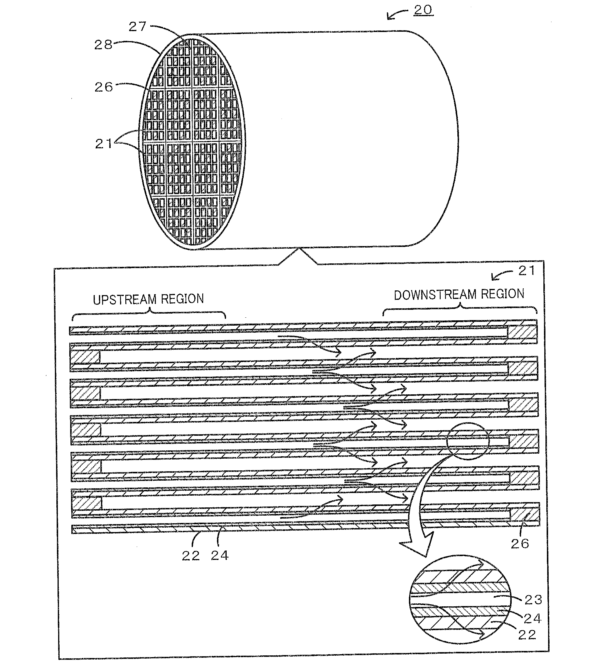
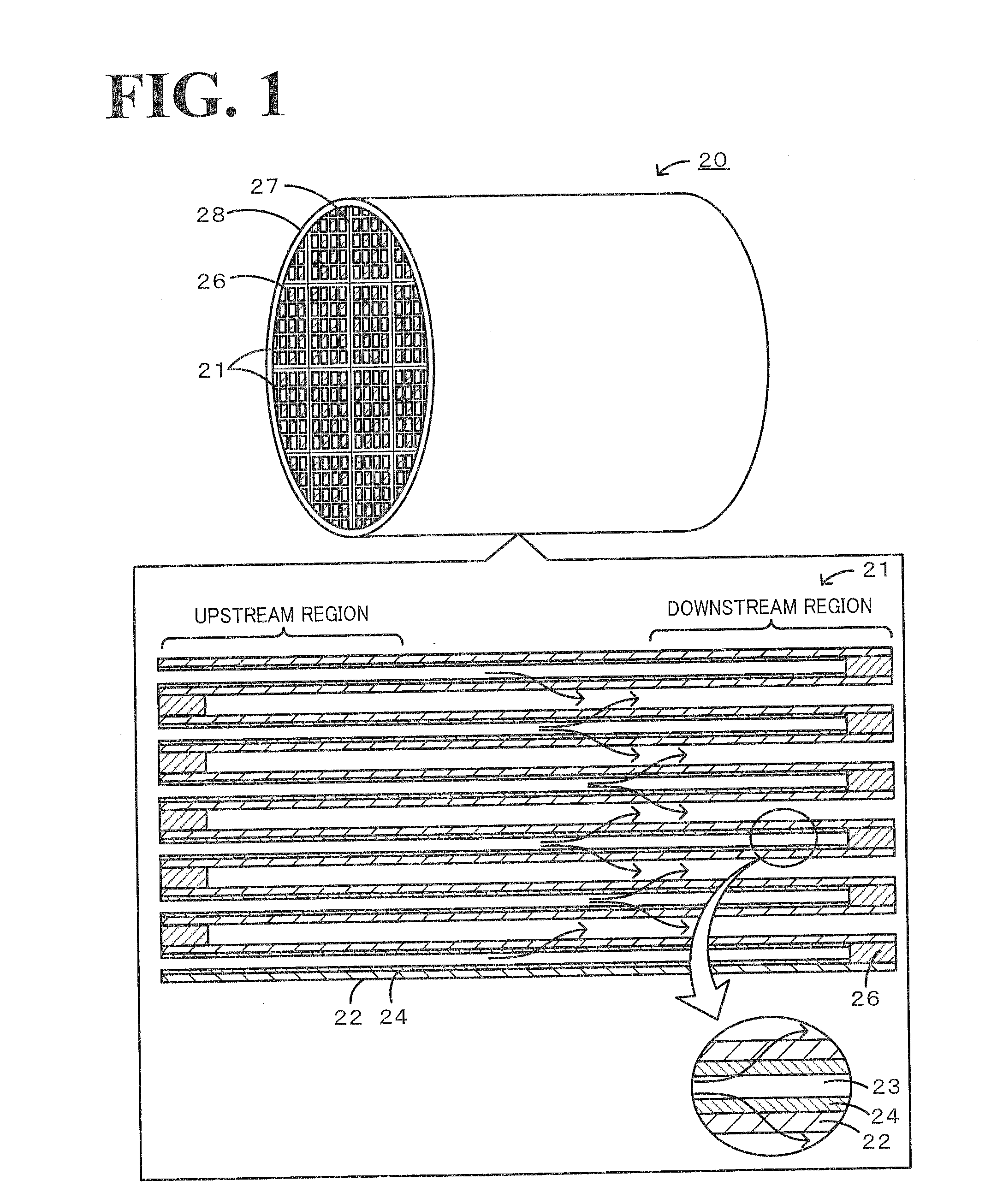
[0048]Hereinafter, examples in which honeycomb filters were specifically produced will be described as experimental examples. Herein, the produced honeycomb filters had a structure in which a plurality of honeycomb segments were bonded together.

[0049]Production of Honeycomb Filter

[0050]A SiC powder and a metal Si powder were mixed at a mass ratio of 80:20. Methylcellulose, hydroxypropoxylmethylcellulose, a surfactant, and water were added to the mixture and the resultant mixture was kneaded to prepare a plastic pug. This pug was extruded with a predetermined die to form honeycomb segment formed bodies having a desired shape. Herein, the formed shape was as follows: the thickness of the partition portions was 305 μm; the cell pitch was 1.47 mm; the cross section was 35 mm×35 mm; and the length was 152 ran. The obtained honeycomb segment formed bodies were then dried with microwaves, further dried with hot air, subsequently sealed, calcined in an oxidizing atmosphere at 550° C. for 3 ...

experimental examples 1 to 7

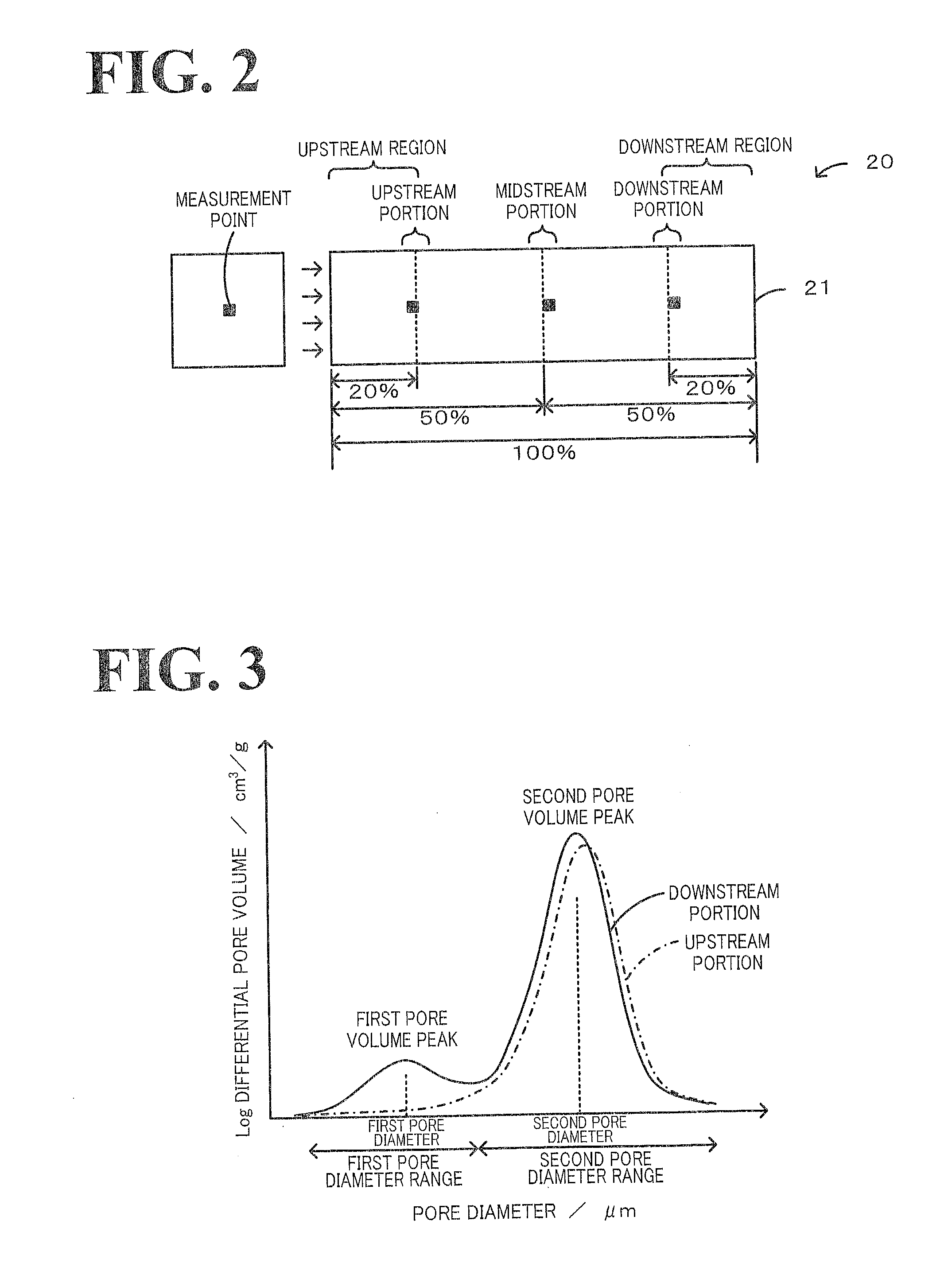
[0057]A honeycomb filter was defined as Experimental example 1 in which the second pore volume peak position was at 14 μm and the porosity was 40% in the upstream and midstream portions of the honeycomb filter, the second pore volume peak was at 14 μm and the porosity was 40% in the downstream portion of the honeycomb filter, and the pore volume difference obtained by subtracting the volume of pores having a diameter of 10 μm or less in the upstream portion from the volume of pores having a diameter of 10 μm or less in the downstream portion (hereafter, simply referred to as pore volume difference) was 0 cm3 / g. A honeycomb filter produced as in Experimental example 1 except that the pore volume difference was made 0.01 cm3 / g was defined as Experimental example 2. A honeycomb filter produced as in Experimental example 1 except that the pore volume difference was made 0.03 cm3 / g was defined as Experimental example 3. A honeycomb filter produced as in Experimental example 1 except that...

experimental examples 8 to 14

[0059]A honeycomb filter was defined as Experimental example 8 in which, in the upstream and midstream portions of the honeycomb filter, the second pore volume peak position was at 14 μm and the porosity was 40%; in the downstream portion of the honeycomb filter, the first pore volume peak position was at 1 μm, the second pore volume peak position was at 14 μm, and the porosity was 40%; and the pore volume difference was 0.04 cm3 / g. A honeycomb filter produced as in Experimental example 8 except that the first pore volume peak position in the downstream portion was made at 2 μm was defined as Experimental example 9. A honeycomb filter produced as in Experimental example 8 except that the first pore volume peak position in the downstream portion was made at 3 μm was defined as Experimental example 10. A honeycomb filter produced as in Experimental example 8 except that the first pore volume peak position in the downstream portion was made at 5 μm was defined as Experimental example 1...


PUM

PropertyMeasurementUnit
diameteraaaaaaaaaa
pore diameteraaaaaaaaaa

Abstract

In a honeycomb filter 20, partition portions and trapping layers are formed such that a pore volume difference that is obtained from pore distributions measured by mercury porosimetry and is a difference in volume of pores having a diameter of 10 μm or less between the downstream portion and the upstream portion of the honeycomb filter, is in the range of 0.01 cm3 / g or more and 0.08 cm3 / g or less. In the honeycomb filter, in the downstream portion, a first pore volume peak is present in a first pore diameter range of 2 μm or more and 9 μm or less and a second pore volume peak that is higher than the first pore volume peak is present in a second pore diameter range of 10 μm or more and 25 μm or less.

Description

BACKGROUND OF THE INVENTION[0001]1. Field of the Invention[0002]The present invention relates to a honeycomb filter.[0003]2. Description of the Related Art[0004]A honeycomb filter has been proposed that has a porous structure in which, when cell partitions have a first pore group of pores having a diameter in the range of 1.0 to 150 μm and a second pore group of pores having a diameter in the range of 0.006 μm or more and less than 1.0 μm in a pore distribution curve, a single peak of the pore diameter distribution is present in the first pore group and a plurality of peaks of the pore diameter distribution are present in the second pore group (for example, refer to Patent Literature 1). It is stated that this filter can achieve trapping and removing of particulate matter (PM) contained in exhaust gas and cleaning of hazardous gas. Another honeycomb filter has been proposed that has partitions having porous partition bases and surface layers provided on the inflow sides of the parti...

Claims


Application Information

Patent Timeline
Patent Type & Authority Applications(United States)
IPC IPC(8): B01D39/14B01D53/88B01D39/20
CPCB01D46/2429B01D2046/2437B01D46/2459B01D46/24492B01D46/2478B01D46/24491
Inventor MIZUTANI, TAKASHIIWASAKI, SHINGO
Owner NGK INSULATORS LTD
Why Eureka
Try Eureka