Low gain pressure relief valve for a fluid pump

Active Publication Date: 2012-10-04
HANON SYST EFP CANADA LTD
View PDF1 Cites 13 Cited by
  • Summary
  • Abstract
  • Description
  • Claims
  • Application Information

AI Technical Summary

Benefits of technology

[0014]In the one exemplary embodiment, the pressure relief valve includes a piston in a bore wherein the bore in the housing includes a counterbore for creating an opening edge/surface interface that is perpendicular to an axis of the relief valve. Thi

Problems solved by technology

While a deprivation of oil can result in damage to engine components, over-pressurized oil is also undesirable.
For example, too high an oil pressure can destroy paper filter elements and have other undesirable effects on the engine and can result in excess power consumption.
Although such a conventional oil pressure relief valve is simple and reliable, it has known limitations and drawbacks that can have an adverse impact on the oil pump's power consumption making it relatively higher.
High power consumption by the oil pump equates to reduced fuel efficiency, which long remains a significant disadvantage.
However, in some circumstances (such as occurs where the valve spring force at the opening position is relatively low as in a pressure relief valve having multiple operating press

Method used


Image

  • Low gain pressure relief valve for a fluid pump
  • Low gain pressure relief valve for a fluid pump
  • Low gain pressure relief valve for a fluid pump

Examples


Embodiment Construction

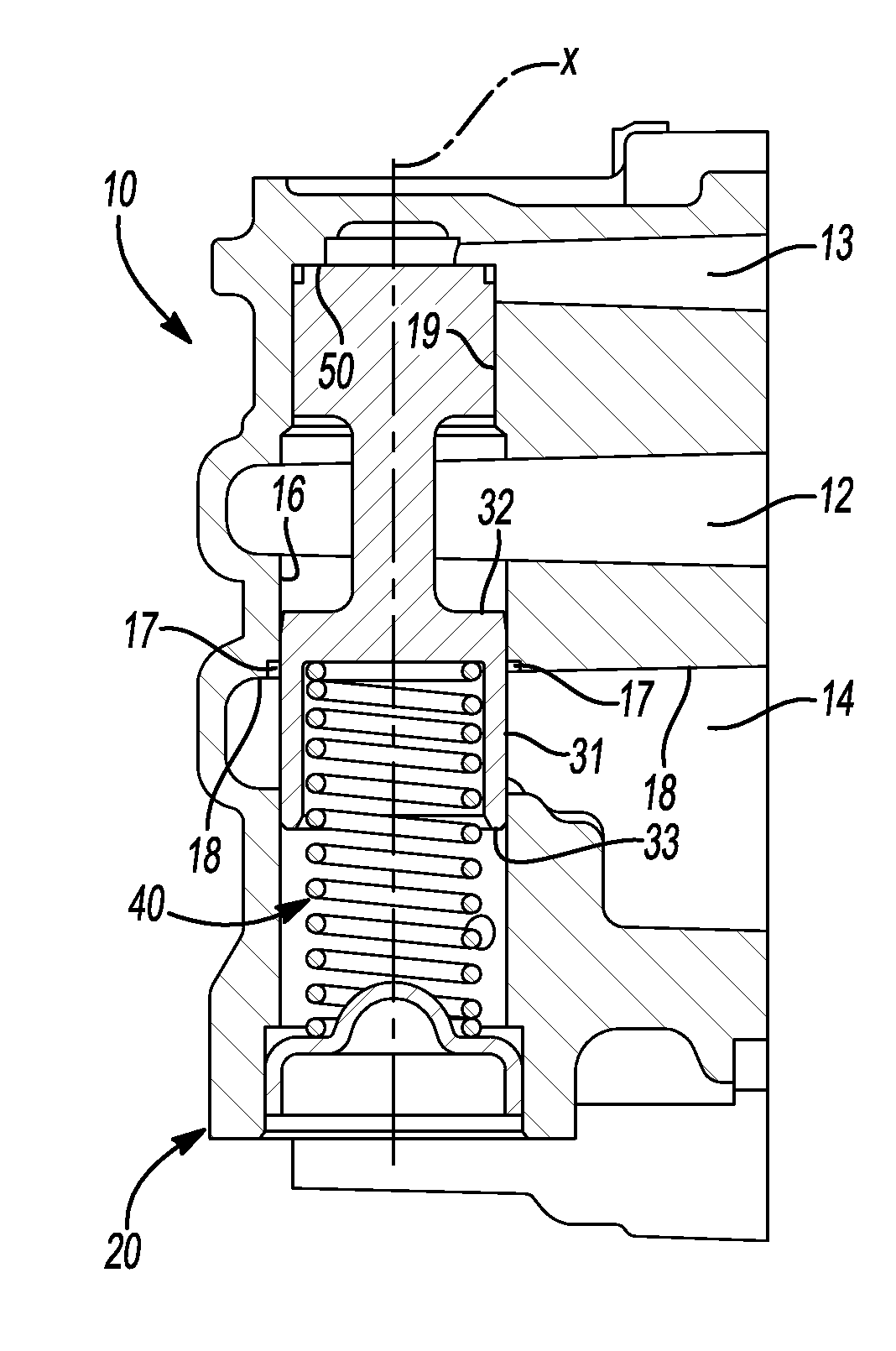
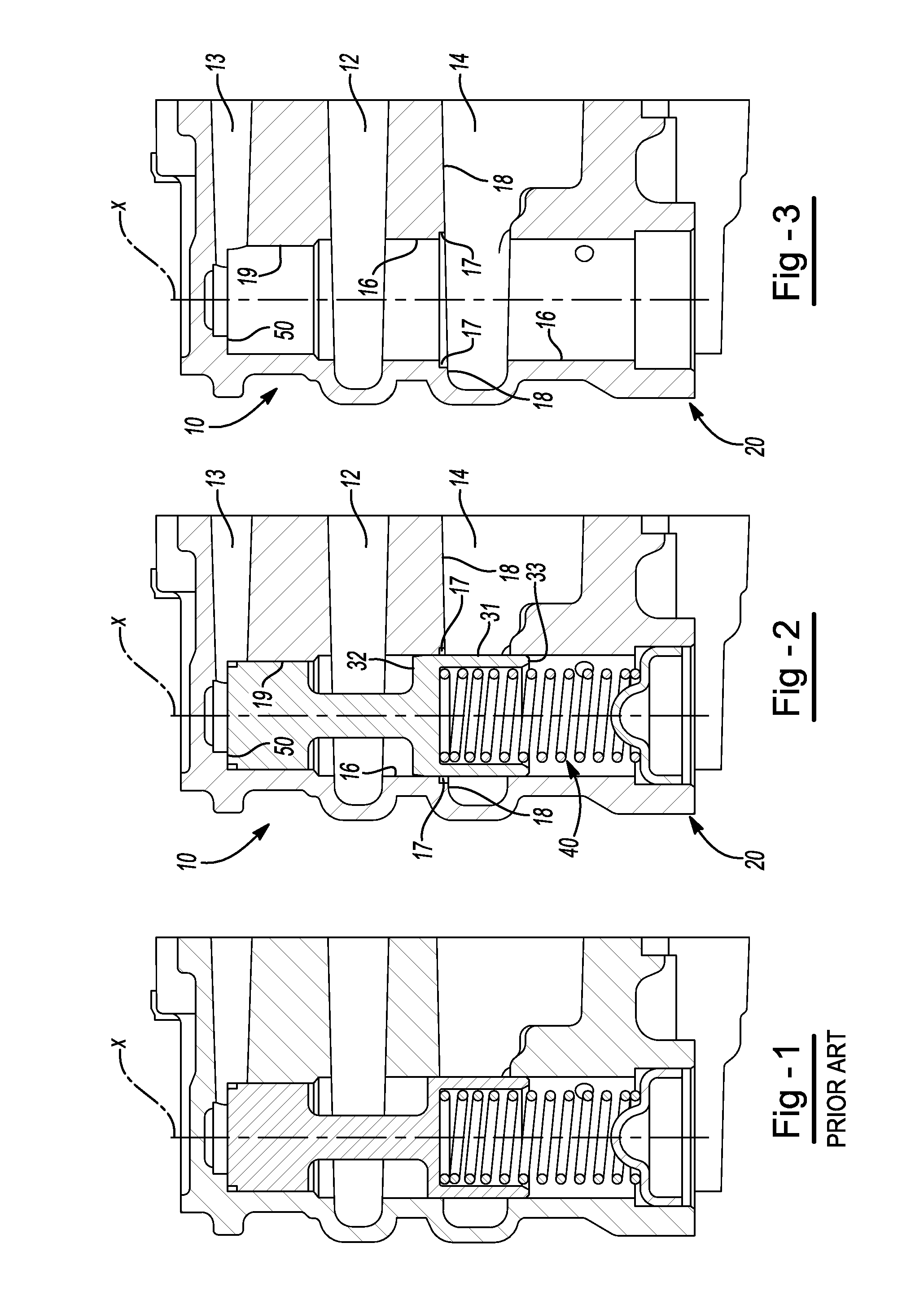
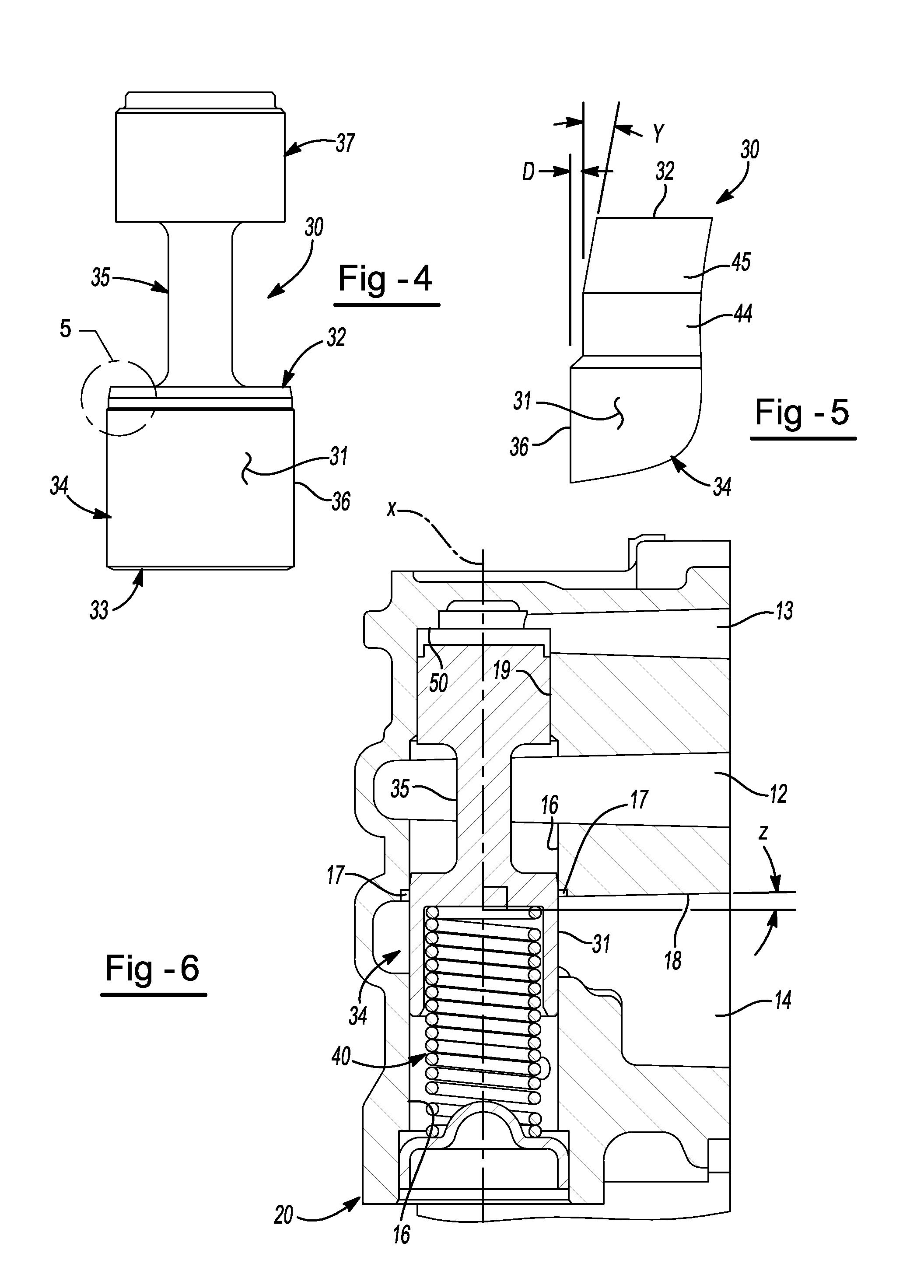
[0034]Referring generally to all of the figures, and in particular to FIG. 2, there is disclosed a new design for a low gain pressure relief valve 10 having particularly utility in a oil pump assembly (not shown) for use in an engine (not shown) such as those used in a vehicle (not shown) and in particular for use in an oil pump in an engine (not shown) in a passenger vehicle (not shown). While the pressure relief valve 10 shown has particular utility in an oil pump assembly for an engine, it should be understood that the pressure relief valve of the present disclosure may have application in similar applications including other known or appropriate applications and environments.

[0035]The low gain pressure relief valve 10 includes a valve housing 20 having a valve body passage or bore 16 extending longitudinally therein. The valve housing 20 may be made an integral part of the oil pump assembly, as is the case for the embodiment shown in FIG. 2, or the valve housing 20 may alternati...


PUM


Abstract

A pressure relief valve for use in regulating discharge fluid pressure of a pump includes a casted, metal material housing including a passage therein along a longitudinal axis and inlet and outlet ports substantially perpendicular to the longitudinal axis and each having walls that are at an angle less than perpendicular to the longitudinal axis wherein the angle of the wall from being perpendicular to the longitudinal axis is substantially equal to the draft angle from the casting of the housing. A first wall of the outlet intersects with the wall of the passage of the pressure relief valve. A valve body disposed in the passage is movable in the passage against the biasing force of a spring biasing the valve body in a first or closed direction wherein the inlet port and the outlet port are disconnected, until the force at the inlet applied to the valve body overcomes the biasing Force of the spring and the inlet fluid is communicated through the passage and to the outlet. The housing includes a counterbore at the intersection of the wall of the passage and the wall of the outlet port to provide a counterbore surface that is perpendicular to the wall of the passage around the outer circumference of the valve body. The top end of the valve body includes a reduced diameter portion and a tapered portion between the reduced diameter portion and the top of the valve body.

Description

CROSS-REFERENCE TO RELATED APPLICATIONS[0001]This application hereby claims priority to, and the benefit of, U.S. application Ser. No. 61 / 470,403, filed Mar. 31, 2011, entitled LOW GAIN PRESSURE RELIEF VALVE FOR A FLUID PUMP, to inventor Matthew Williamson, the entire contents of which is incorporated herein for all benefits and purposes.FIELD[0002]The present disclosure relates generally to an oil pump assembly including a low gain pressure relief valve for managing oil pump discharge pressure in an engine. More particularly, the present disclosure relates to a pressure relief valve having particular application in a pump of a lubrication system in an internal combustion engine of a vehicle.DISCUSSION OF RELATED ART[0003]It is generally known to provide an internal combustion engine including an oil pump assembly for pumping engine oil through the engine to lubricate the engine components through the various lubrication channels in the engine (also generally known as passageways an...

Claims


Application Information

Patent Timeline
IPC IPC(8): F16K1/00
CPCF01M1/16F16K17/04Y10T137/8671
Inventor WILLIAMSON, MATTHEW
Owner HANON SYST EFP CANADA LTD
Why Eureka
Try Eureka