Organic electroluminescent element

a technology of electroluminescent elements and organic materials, which is applied in the direction of electroluminescent light sources, organic semiconductor devices, thermoelectric devices, etc., can solve the problems of difficult to achieve emission in these various hues of white without incurring changes in chromaticity within the range of jis standards, and achieve high emission efficiency, good emission balance, and long life

Inactive Publication Date: 2012-10-04
PANASONIC CORP
View PDF3 Cites 40 Cited by
  • Summary
  • Abstract
  • Description
  • Claims
  • Application Information

AI Technical Summary

Benefits of technology

[0005]In the light of the above, it is an object of the present invention to provide an organic electroluminescent element, in particular a high-efficiency, long-life white-emission organic electroluminescent element, that boasts high emission efficiency, long life, and also good emission balance

Problems solved by technology

The layer of this blue fluorescent material exhibited readily changes in chromaticity; this was accordingly problematic, in terms of life contingent on the amount of change in chromaticity, in that the life of the organic electroluminescent element was shortened.
Also, white emission encompasses various specific hues, namely D, N, W, WW and L, and it was difficult to achieve emission in these various hues of white without incurring changes in chromaticity within the ranges of JIS standards.

Method used


Image

  • Organic electroluminescent element
  • Organic electroluminescent element
  • Organic electroluminescent element

Examples


examples

[0089]Examples of the present invention are explained next.

[0090][Production of Organic Electroluminescent Elements]

[0091]Organic electroluminescent elements of examples and comparative examples were produced according to the procedure below.

[0092]The anode 4b having a sheet resistance of 10 Ω / square was formed, by sputtering of ITO (indium-tin oxide) onto a 0.7 mm-thickness glass substrate, as the substrate 5, to produce a glass substrate provided with ITO. The glass substrate provided with ITO was subjected to ultrasonic cleaning for 15 minutes with acetone, pure water and isopropyl alcohol, and was then dried and cleaned using UV ozone. The glass substrate provided with ITO was then set in a vacuum vapor deposition apparatus, and various organic or inorganic layers were sequentially vapor-deposited, through resistance heating, under a degree of vacuum of 5×10⁻⁵ Pa or less. Lastly, Al was vapor-deposited to form the cathode 4a.

[0093](Device Structure of the Organic Electrolumines...

examples 1 to 5

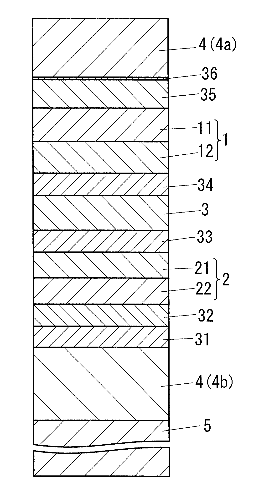
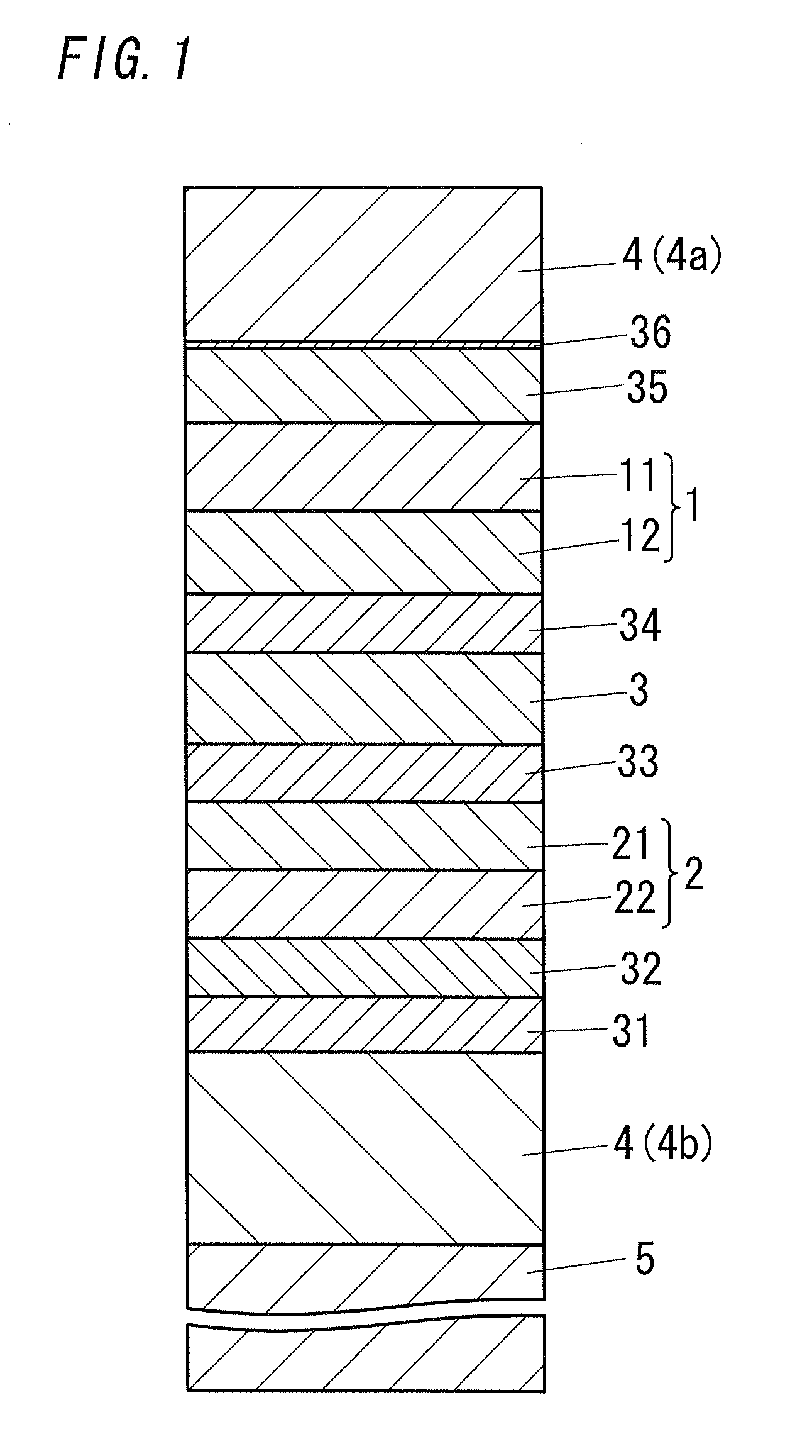
[0094]The device structure (layer build-up) and film thickness of the various layers are given below. The layer build-up in Examples 1 to 5 is identical to that of FIG. 1. However, the interlayer 3 comprises two layers, namely a first layer and a second layer.

Substrate 5: glass substrate (0.7 mm)

Anode 4b: ITO (150 nm)

Hole injection layer 31: CuPc (30 nm)

Role transport layer 32: The (30 nm)

Blue fluorescent light-emitting layer 22: TBADN: TBP: NPD (X nm)

Green fluorescent light-emitting layer 21: Alq3: C545T (Y nm)

Electron transport layer 33: BCP (30 nm)

Interlayer 3 (first layer): BCP: Li (10 nm)

Interlayer 3 (second layer) ITO (10 nm)

Hole transport layer 34: TPD (30 nm)

Red phosphorescent light emitting-layer 12: CBP: Btp2Ir(acac) (α nm)

Green phosphorescent light emitting-layer 11: CSP: Ir(ppy)3 (β nm)

Electron transport layer 35: BCP (20 nm)

Electron injection layer 35: LiF (1 nm)

Cathode 4a: Al (80 nm)

[0095]The various light-emitting layers in the above organic electroluminescent element...

examples 6 to 10

[0104]The organic electroluminescent elements in Examples 6 to 10 were produced in the same way as in Examples 1 to 5, but herein the green fluorescent light-emitting lever 21 of the fluorescent light unit 2 in the organic electroluminescent elements of Examples 1 to 5 was as follows.

[0105]Green fluorescent light-emitting layer 21: rubrene (Y nm)

[0106]In the green fluorescent light-emitting layer 21, a light-emitting layer host Alq3 was doped with 2% of a green emitting dopant: rubrene. The green fluorescent light-emitting layer 21 utilizes rubrene, which gives rise to visually yellow emission, and thus is also referred to as a yellow fluorescent light-emitting layer. The film thicknesses are as shown in Table 1.


PUM


Abstract

Disclosed is a high-efficiency, long-life white-emission organic electroluminescent element, in particular, a white-emission organic electroluminescent element. The organic electroluminescent element of the present invention has a red phosphorescent light emitting-layer 12; a green phosphorescent light emitting-layer 11; a blue fluorescent light-emitting layer 22 and a green fluorescent light-emitting layer 21. A phosphorescent light unit 1 is formed by the red phosphorescent light emitting-layer 12 and the green phosphorescent light emitting-layer 11. A fluorescent light unit 2 is formed by the blue fluorescent light-emitting layer 22 and the green fluorescent light-emitting layer 21. The phosphorescent light unit 1 and the fluorescent light unit 2 are connected via an interlayer 3. Preferably, the phosphorescent light unit 1 is disposed further towards a cathode 4a side than the fluorescent light unit 2. Preferably, the emission color is any of a W color, a WW color and an L color.

Description

TECHNICAL FIELD[0001]The present invention relates to an organic electroluminescent element, and more particularly to an organic electroluminescent element that is appropriate for white emission.BACKGROUND ART[0002]It is known that organic electroluminescent elements are formed through stacking of an organic material layer, in the form of a single layer or a plurality of layers, between an electrode and another electrode. In such an organic electroluminescent element, one of the electrodes is an anode and the other electrode is a cathode, and voltage applied across both electrodes elicits recombination of electrons, which are injected and transported into the organic material layer from the cathode side, with holes that are injected and transported from the anode side. Light emission is obtained as a result of this recombination. Organic electroluminescent elements are thin light-emitting elements that afford surface emission, and that have received attention in recent years as cons...

Claims


Application Information

Patent Timeline
Patent Type & Authority Applications(United States)
IPC IPC(8): H01L51/54
CPCH01L51/504H01L51/5278H05B33/14H05B33/10H01L2251/5376H10K50/13H10K50/19H10K2101/27
Inventor SASAKI, HIROYUKI
Owner PANASONIC CORP
Why Eureka
Try Eureka