
Fluorescent nanoparticle composites themselves, process for the preparation of such composites, and use in rapid diagnosis systems with affinity to biological molecules

Active Publication Date: 2012-10-04
UFPE
View PDF1 Cites 6 Cited by
  • Summary
  • Abstract
  • Description
  • Claims
  • Application Information

AI Technical Summary

Benefits of technology

[0041]It is yet another object of the present invention to provide the use of the fluorescent composites of the invention for the preparation of photovoltaic devices, such as solar cells, electroluminescent devices, such as organic LEDs, sensors, or for the increase in the lighting efficiency of fluorescent lamps.

Problems solved by technology

However, one should point out that some of these techniques still have some limitations, such as false-positive signals, that can lead to an error in diagnosis.

Method used


Image

  • Fluorescent nanoparticle composites themselves, process for the preparation of such composites, and use in rapid diagnosis systems with affinity to biological molecules
  • Fluorescent nanoparticle composites themselves, process for the preparation of such composites, and use in rapid diagnosis systems with affinity to biological molecules
  • Fluorescent nanoparticle composites themselves, process for the preparation of such composites, and use in rapid diagnosis systems with affinity to biological molecules

Examples


example 1

Synthesis and Characterization of the Nanoparticles

example 1.1

Preparation of the Nanoparticles

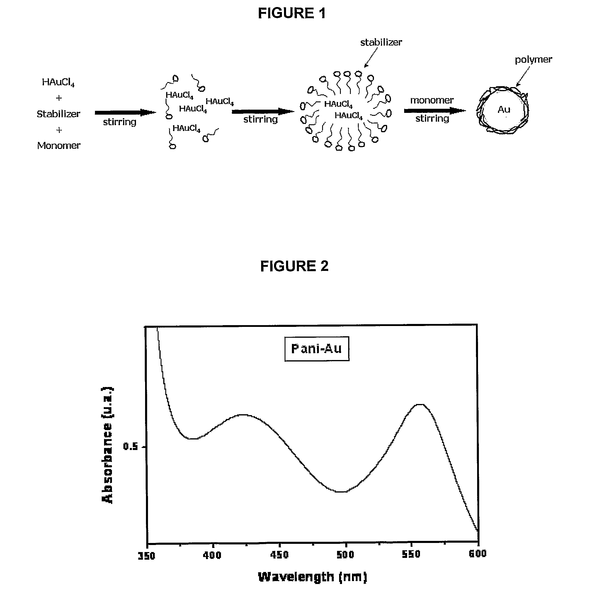
[0062]The preparation of nanoparticles was performed (see scheme in FIG. 1) in a round bottom glass flask containing ethanol (20 mL) and the compounds: aniline (Ani-C6H5NH2) (0.030 mol / L), 3-mercaptopropyl-trimethoxy-silane (MPS-C6H16O6SSO (6.46×10⁻² mol / L) and HAuCl4.xH2O (0.81 mmol / L), which were subsequently added and subject to energetic agitation (1,100 rpm). Aniline (Ani-C6H5NH2) was acquired from VETEC (Brazil) and only used after distillation in a Kugelrohr apparatus. The other compounds were bought from Aldrich Co. (USA), and had at least 99% degree of purity. All subsequent experiments were performed in the 48 hours time interval after the mixtures.

example 1.2

Characterization of the Nanoparticles

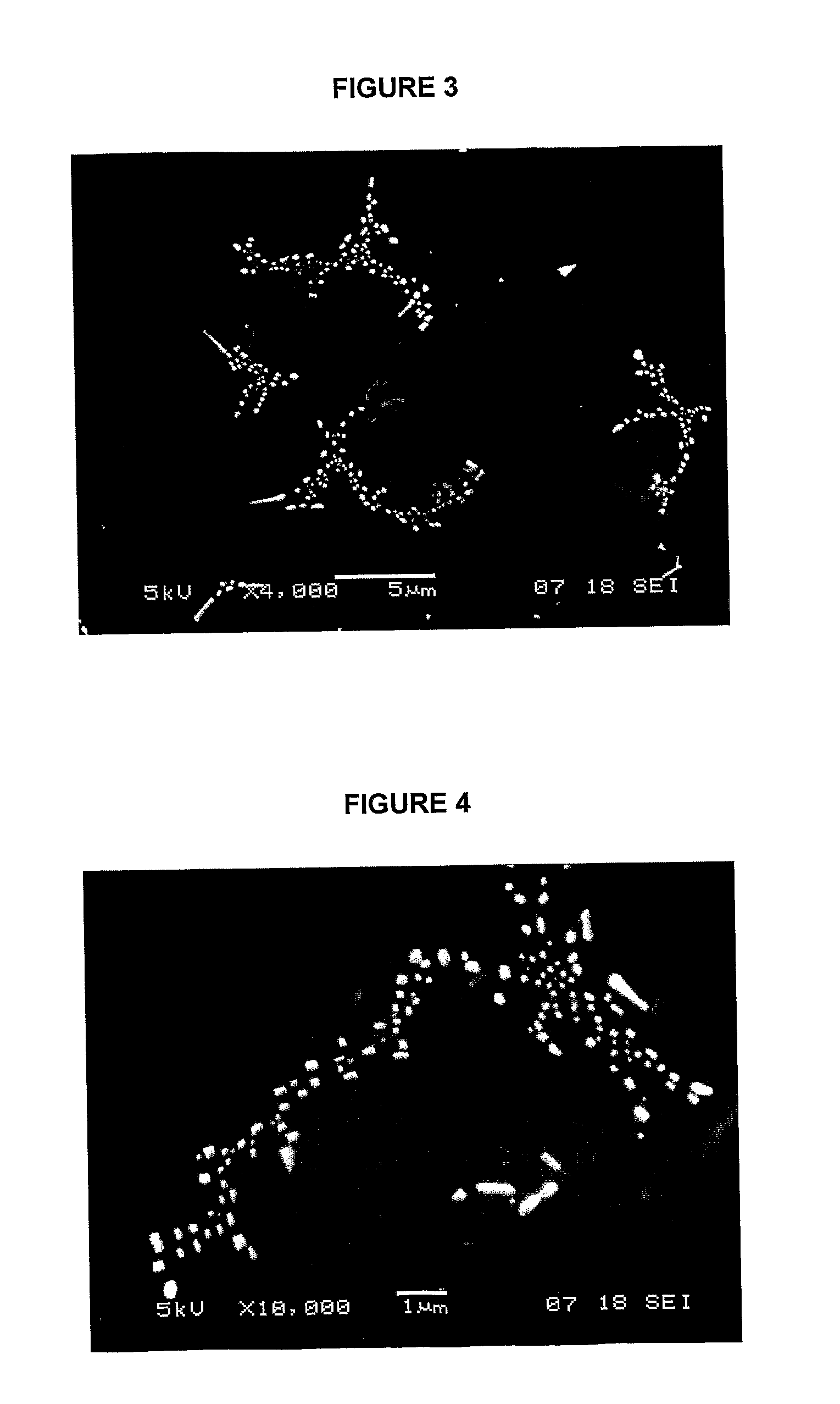
[0063]Photoluminescence properties were measured by use of a quartz cuvette (1 cm and 5 mL) in a PC1 (ISS, USA) spectrofluorimeter at (20±1)° C. The samples were monitored at different pH values by use of two luminescence matrices: (1) in the 200 to 360 nm excitation range and emission in the 370 to 600 nm interval; and (2) in the 270 to 330 nm excitation range and emission in the 280 to 600 nm interval. Morphological analyses were performed by scanning electron microscopy (SEM), by use of a JSM-5900 (JEOL, Japan) electron microscope. The samples were placed atop a glass substrate and fixed by a carbon tape. After this, the samples were covered by a thin gold layer by use of a sputtering (BalTec SCD 050). The size of the particles was determined by a light-scattering method by use of a Zetasizer Nano-ZS90 instrument (Malvern).


PUM

PropertyMeasurementUnit
Digital informationaaaaaaaaaa
Nanoscale particle sizeaaaaaaaaaa

Abstract

The present invention provides fluorescent nanoparticle composites themselves, the process of preparing such composites, to systems for rapid diagnosis (as “kits”) containing such composites, and to the use of such composites. In a preferential embodiment, the composites of the present invention have an affinity for biological molecules, such as DNA. The present invention also comprises the preparation of probes containing biological material, upon which are added fluorescent nanoparticle composites, making viable a rapid and economic biological diagnosis of, for example, diseases and genetic traits, notably in the medical and veterinarian fields. There is yet the fact that the absorption of radiation in the ultraviolet and visible regions, with the emission of light in the near ultraviolet and visible range, including in the colors of deep blue and / or green, provides advantageous use of its fluorescent properties in photovoltaic or electroluminescent devices, such as organic LEDs, or for the increase in luminous gain of fluorescent lamps, which represents another characteristic of the invention.

Description

FIELD OF THE INVENTION [0001]The present invention refers to fluorescent nanoparticle composites. More specifically, it refers to the composites themselves, to the process of preparing such composites, to systems for rapid diagnosis (as “kits”) containing such composites, and to the use of such composites. In particular, the composites of the present invention provide, among other advantages the absorption of radiation in the ultraviolet and visible regions, with the emission of light in the near ultraviolet and visible range, including in the colors of deep blue and / or green, providing advantageous use of its fluorescent properties in photovoltaic or electroluminescent devices, such as organic LEDs, or for the increase in luminous gain of fluorescent lamps. Besides that, the composites of the present invention have an affinity for biological molecules, such as DNA and RNA, also providing for applications in the medical and veterinarian fields, and in the diagnosis of genetic diseas...

Claims


Application Information

Patent Timeline
IPC IPC(8): G01N21/64C09K11/07C09K11/06B82Y15/00B82Y30/00B82Y40/00
CPCG01N33/533G01N33/582G01N33/587Y10S977/902Y10S977/773Y10S977/84Y10S977/704C08G73/0266C09K11/06C09K2211/14C12Q1/6834C12Q1/701C12Q1/708
Inventor PINTO DE MELO, CELSODE ANDRADE, CESAR AUGUSTO SOUZADOS SANTOS, CLECIO GOMES
Owner UFPE
Learn More