Methods and systems for predicting ship motion

a technology for predicting ship motion and methods, applied in the direction of electric devices, process and machine control, instruments, etc., can solve the problems of inability to monitor conditions over the horizon, and inability to monitor the activity of longer-range waves

Active Publication Date: 2012-10-04
THE BOEING CO
View PDF1 Cites 28 Cited by
  • Summary
  • Abstract
  • Description
  • Claims
  • Application Information

AI Technical Summary

Benefits of technology

[0007]In one aspect, a ship motion prediction system is provided that includes a plurality of surface platforms and a central computer having a communications interface. The platforms each include a propulsion system for movement of the platform, a plurality of sensors operable for gathering sensor data relating to an environment proximate a platform, a processing device communicatively coupled to the propulsion system and the plurality of sensors, and a transceiver communicatively coupled to the processing device. The central computer includes a comm

Problems solved by technology

Using radar to monitor waves presents a variety of limitations.
For example, X-band radar is a short range line-of-sight solution, and is unable to monitor conditions over the horizon.
Furthermore, longer range wave activity can be blocked by large closer waves.
Slow update rates makes it difficult or impossible to track an individual wave train, and/or determine wave velocity.
LIDAR is a line-of-sight optical system and is impaired by cloud cover, fog, and rain.
An airborne radar solution or LIDAR could be deployed by UAVs (unmanned airborne vehicles), but such solutions require special platforms and equipment to deploy and recover, as well as being prohibitively expensive to operate.
Traditional buoys need t

Method used


Image

  • Methods and systems for predicting ship motion
  • Methods and systems for predicting ship motion
  • Methods and systems for predicting ship motion

Examples


Embodiment Construction

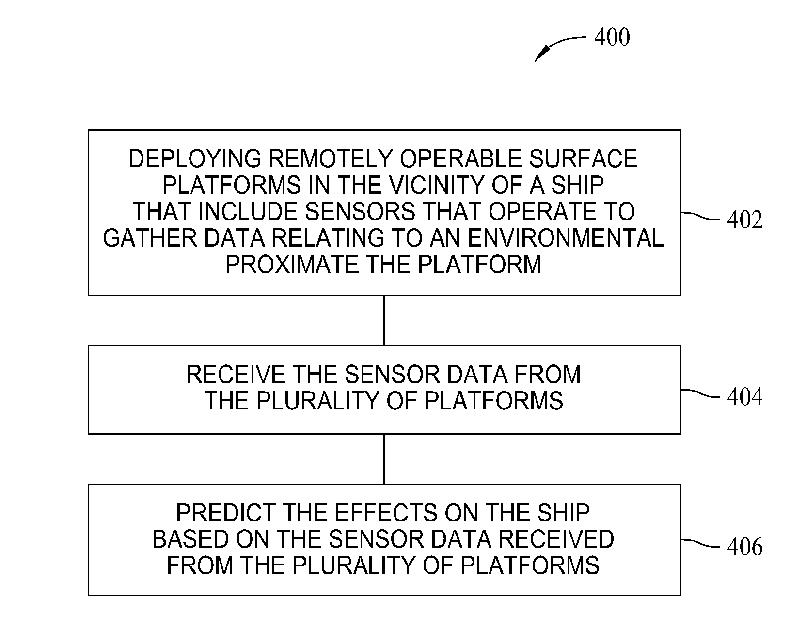
[0016]The described embodiments are directed to methods and systems for predicting ship motion. Specifically, an apparatus and a process of measuring wave motion (i.e., height, period, direction, and speed) are described for the purpose of predicting the motions of one or more ships while conducting launch, recovery, loading, or unloading operations. As further described, application of the described embodiments may occur in the open ocean, in coastal waters, or in inland waters, in water of any depth, and while the ship or ships are stationary or under way.

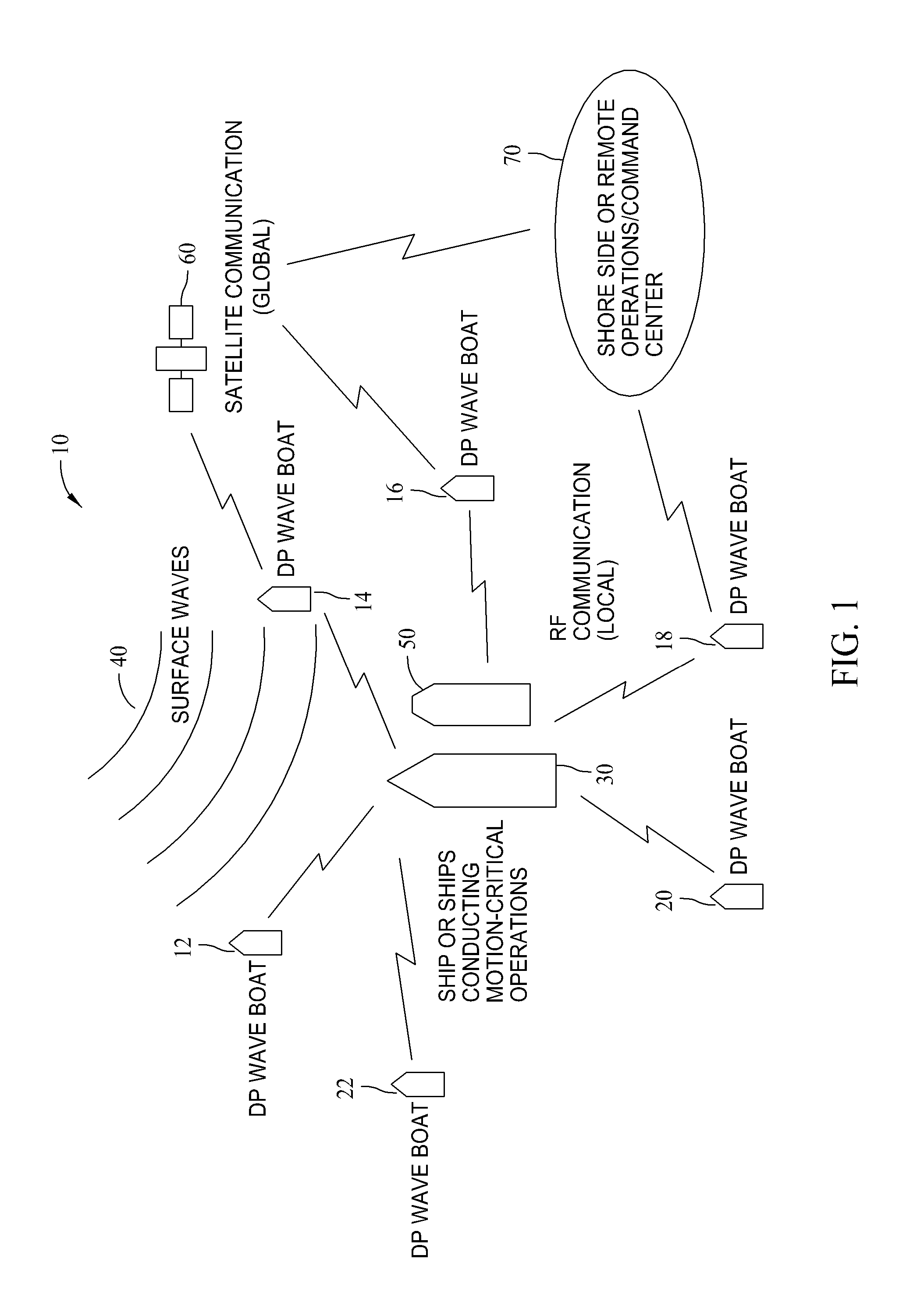
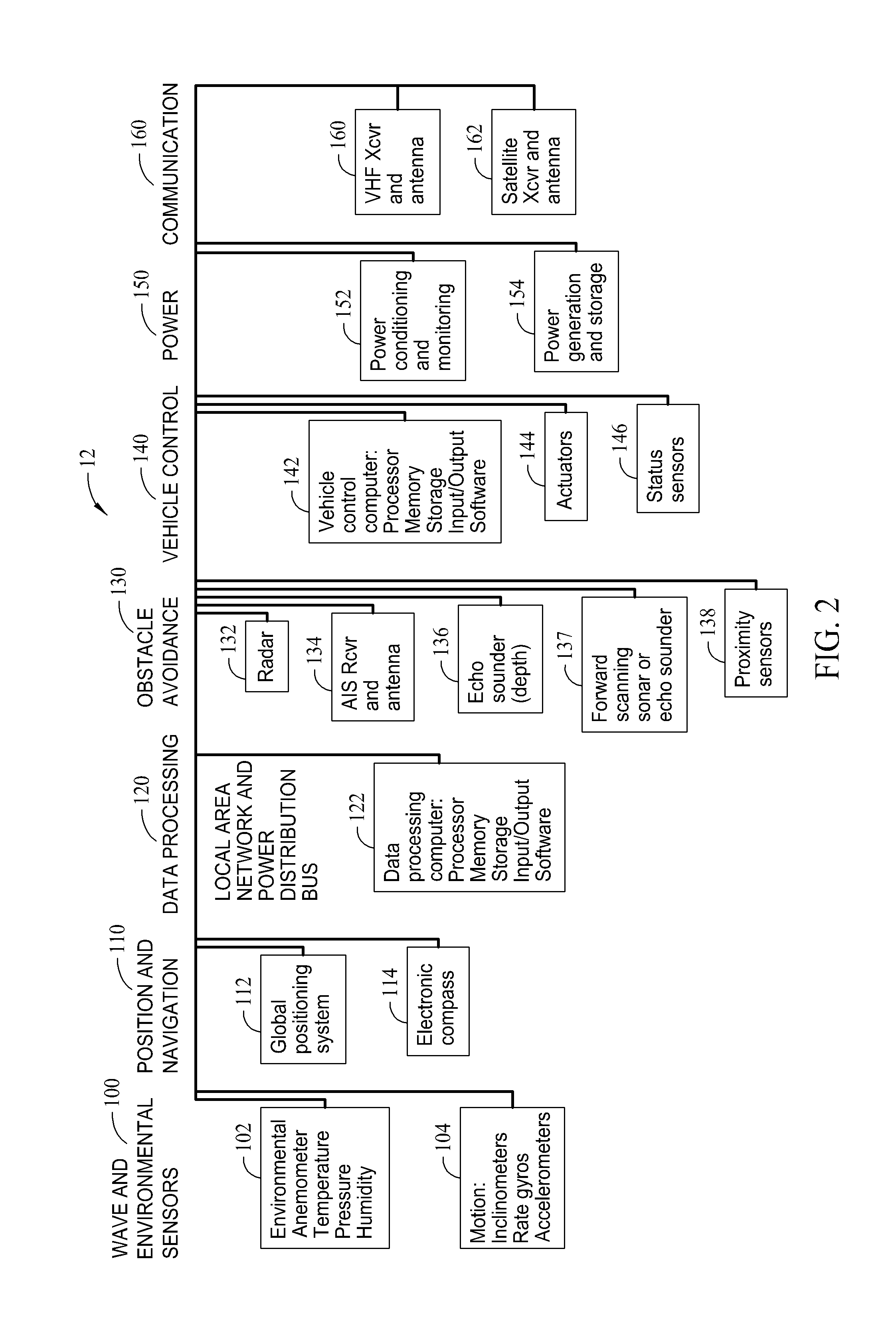
[0017]FIG. 1 is an illustration of a ship motion prediction system 10 which includes a plurality of mobile surface platforms 12, 14, 16, 18, 20, and 22. Mobile surface platforms 12, 14, 16, 18, 20, and 22 are sometimes referred to as wave monitoring devices or “wave boats”. In various embodiments, and as further explained herein, mobile surface platforms 12, 14, 16, 18, 20, and 22 are programmed to operate autonomously, can be re...


PUM


Abstract

A ship motion prediction system is described that includes a plurality of surface platforms and a central computer having a communications interface. The platforms each include a propulsion system for movement of the platform, a plurality of sensors operable for gathering sensor data relating to an environment proximate the platform, a processing device communicatively coupled to the propulsion system and the plurality of sensors, and a transceiver communicatively coupled to the processing device. The central computer includes a communications interface, and the processing device is programmed to transmit sensor data to the central computer via the transceiver and the communications interface. The central computer is programmed to transmit commands for operation of the propulsion system to the processing device via the communications interface and transceiver. The central computer is further programmed to predict an effect of the environments associated with the plurality of surface platforms on a water vessel or vessels operating within a vicinity of the plurality of surface platforms.

Description

BACKGROUND[0001]The field of the disclosure relates generally to motion of ships in bodies of water, and more specifically, to methods and apparatus for predicting ship motion.[0002]Ship motions are affected by local waves, currents, and wind in combination with the ship's speed, direction, loading, weight distribution, hull shape, and other parameters. In order to predict ship motion, it is necessary to know in advance what the wave motions, current, wind, and other environmental conditions are in the vicinity of the ship. Since waves, current, and wind travel at various speeds and directions, and the ship itself may also be under way, it is desirable to monitor these conditions at significant distances away from the ship so that it can be determined in advance if the waves, current, and wind are heading in a direction that will eventually impart one or more motions onto the ship.[0003]Waves and surface currents can be monitored by radar, light detection and ranging (LIDAR) systems...

Claims


Application Information

Patent Timeline
IPC IPC(8): G05D1/02
CPCG08G3/02B63B2035/008B63B79/40B63B79/15G05D1/0875
Inventor BALLOU, PHILIP J.CHEN, HENRY
Owner THE BOEING CO
Why Eureka
Try Eureka