Microfabrication of Tunnels

a tunnel and microfabrication technology, applied in the field of hollow bore formation, can solve the problems of slipping off center, limited accuracy of drilled depth, and inability to reliably and precisely form very small holes of arbitrary shape for long lengths

Active Publication Date: 2012-10-11
THE UNITED STATES OF AMERICA AS REPRESENTED BY THE SECRETARY OF THE NAVY
View PDF8 Cites 6 Cited by
  • Summary
  • Abstract
  • Description
  • Claims
  • Application Information

AI Technical Summary

Benefits of technology

[0009]The invention satisfies the above-described and other needs by providing for a method of forming hollow bores by positioning one or more forms, such as fibers or sheets, above a substrate, and applying a photoresist over the substrate embedding the one or more forms.

Problems solved by technology

However, these methods are all limited in their ability to reliably and precisely form very small holes of arbitrary shape for long lengths.
In the (a) drilling round holes methods, drilling a beam tunnel typically limits the cross sectional shape to round, and has a limited depth that the bore can be drilled to accurately.
Furthermore, during drilling, there is a tendency to walk off-center, and the method relies on extremely fragile micro-drill bits.
In brazing, stresses due to cyclical heating typically tend to separate the two halves where they were joined, which can reduce reliability.
The (d) laser ablation method is typically limited in the depth of the cut.
In the (f) casting method, molten metal around a mold requires the forms to be subjected to high temperatures, which can introduce issues of thermal expansion, can complicate the removal of the molds, and typically has a tendency to leave gaps and voids in the casting.
In the case of some pure metals such as copper, cast melting tends to form large crystal grains, which are typically unable to fill the smallest features properly.
Finally, (g) conventional multi-layer LIGA techniques require a minimum of three layers, each requiring a separate exposure step, electroforming step and polishing step, and these techniques are only capable of square or rectangular beam tunnel shapes or approximations to true cylinders.

Method used


Image

  • Microfabrication of Tunnels
  • Microfabrication of Tunnels
  • Microfabrication of Tunnels

Examples


Embodiment Construction

[0017]Referring now to the drawings, in which like numerals represent like elements, aspects of the exemplary embodiments will be described in connection with the drawing set.

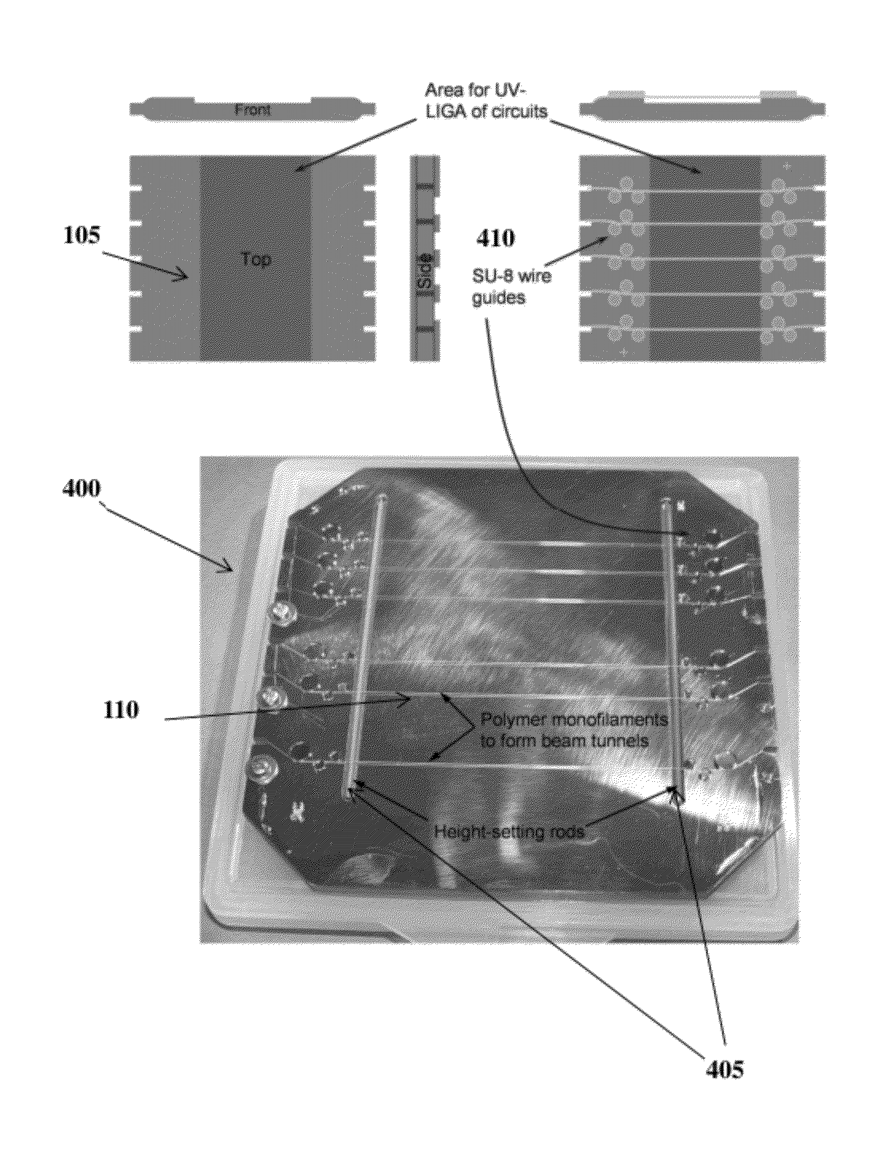
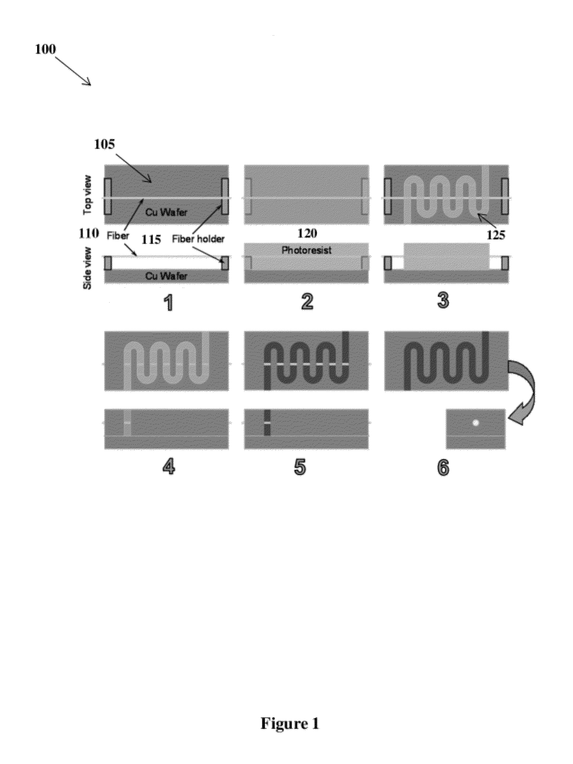
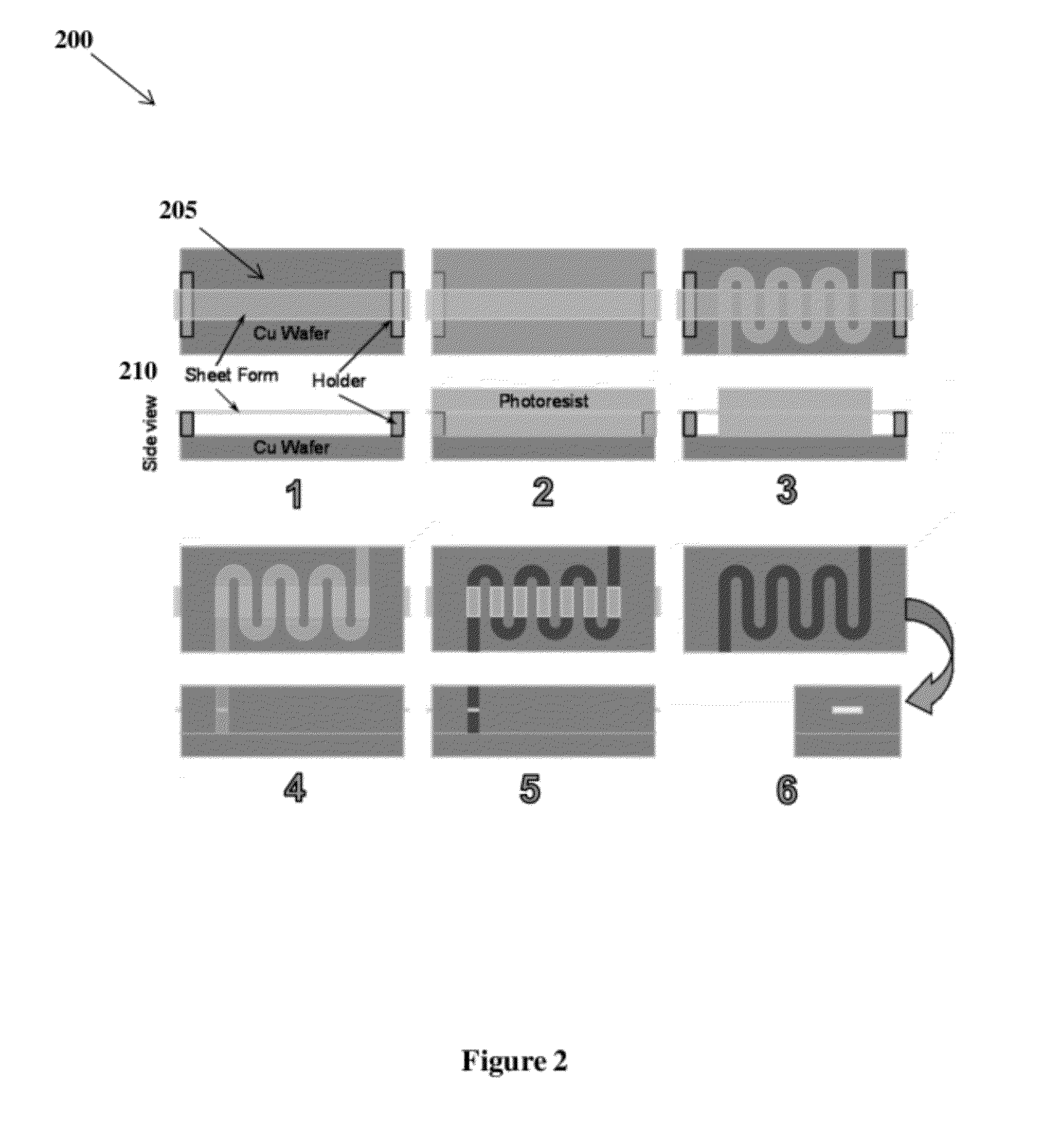
[0018]In general, this invention is a method to form arbitrarily shaped cross sections of a hollow bore, or beam tunnel, of arbitrary length by means of forms, such as fibers or sheets, stretched over the surface that are substantially transparent to ultraviolet light such that a 3-D mold structure is formed by intersection of these forms with structures formed out of photoresist during an exposure to the ultraviolet light using photolithographic techniques.

[0019]FIG. 1 is a top and side view of the methodology of the invention in accordance with an exemplary embodiment of the invention. Specifically, FIG. 1 represents individual steps, illustrated as panels, which will be discussed below. One of ordinary skill in the art will understand that some minor steps, such as cleaning steps, polishing steps, and / or bak...


PUM

PropertyMeasurementUnit
lengthaaaaaaaaaa
diameteraaaaaaaaaa
diameteraaaaaaaaaa

Abstract

A system and method to form beam tunnels in interaction circuits. Forms, such as fibers or sheets can be located and secured above a substrate at a desired size and desired shape to form the final shape of the beam tunnels. Fiber holders can be utilized to position the forms above the substrate. A photoresist can then be applied over the substrate embedding the forms. A single exposure LIGA process can be performed on the photoresist, including the steps of ultraviolet photolithography, molding, and electroforming. After the process, the forms can be removed to leave the beam tunnels in the interaction circuits.

Description

CROSS-REFERENCE TO RELATED APPLICATIONS[0001]The application claims priority to U.S. Provisional Patent Application entitled, “Microfabrication of Tunnels in Metal for Electron Beams Using Photolithography,” filed on Apr. 5, 2011, and assigned U.S. application Ser. No. 61 / 471,828; the entire contents of which are hereby incorporated by reference.FIELD OF THE INVENTION[0002]The invention relates to forming hollow bores. More specifically, the invention relates to a method for forming any number of very small, precise high-aspect-ratio hollow bores, or “beam tunnels,” of arbitrary cross sectional shape and arbitrarily long length in metals for the purpose of transporting electron beams.BACKGROUND[0003]Vacuum electron devices that generate electromagnetic power in the gigahertz (GHz=109 Hz) to terahertz (THz=1012 Hz) frequency range often rely on very small metal structures, known as “interaction circuits,” that support electromagnetic fields which interact with a beam of electrons in ...

Claims


Application Information

Patent Timeline
Patent Type & Authority Applications(United States)
IPC IPC(8): C25D1/10C25D1/02G03F7/004
CPCC25D1/003C25D1/02G03F7/00
Inventor JOYE, COLIN D.
Owner THE UNITED STATES OF AMERICA AS REPRESENTED BY THE SECRETARY OF THE NAVY
Why Eureka
Try Eureka