Injection valve

Inactive Publication Date: 2012-10-11
ROBERT BOSCH GMBH
View PDF3 Cites 9 Cited by
  • Summary
  • Abstract
  • Description
  • Claims
  • Application Information

AI Technical Summary

Benefits of technology

[0004]In contrast, the injection valve according to the invention has the advantage that injection behavior is improved. Specifically, defined injection jets can be re

Problems solved by technology

In the case of a spray device for fluids having a shock-wave actuator, the problem arises that operation has to be carried out counter to

Method used


Image

  • Injection valve
  • Injection valve

Examples


Embodiment Construction

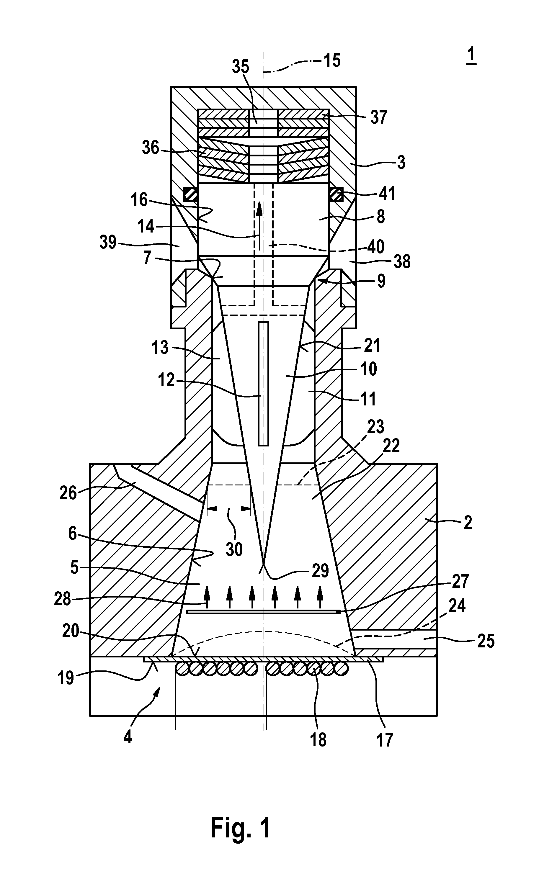
[0018]FIG. 1 shows a first exemplary embodiment of an injection valve 1 in a partial, diagrammatic sectional illustration. The injection valve 1 can serve, in particular, as an injector 1 for fuel injection systems. An injector 1 of this type can be used for air-compressing, compression-ignition internal combustion engines or for mixture-compressing, spark-ignition internal combustion engines. Specifically, the injection valve 1 can serve for the injection of diesel fuel or of gasoline into a combustion chamber of an internal combustion engine. However, the injection valve 1 can also be used for an exhaust-gas aftertreatment system, for example for the injection for DeNOx systems. However, the injection valve 1 according to the invention is also suitable for other applications.

[0019]The injection valve 1 has an injector body 2, an injector sleeve 3 which is connected to the injector body 2, and a shock-wave actuating system 4. Here, the shock-wave actuating system 4 is arranged in t...


PUM


Abstract

The invention relates to an injection valve (1), which is used in particular as an injector for fuel injection systems or exhaust gas aftertreatment systems, comprising a shock wave actuator (4), a valve closing body (8) that interacts with a valve seat surface (7) to form a sealing seat (9), and a shock wave amplification channel (22). The shock wave amplification channel (22) is used to conduct shock waves (27) generated by the shock wave actuator (4) to the sealing seat (9) and to amplify said shock waves (27).

Description

BACKGROUND OF THE INVENTION[0001]The invention relates to an injection valve, in particular an injector for fuel injection systems or for exhaust-gas aftertreatment systems.[0002]DE 10 2006 026 153 A1 has disclosed a spray device for fluids. The known spray device has a nozzle and an actuator for regulating the fluid flow through the nozzle outlet. Moreover, a shock-wave actuator is provided for generating shock waves in the fluid which is situated in the nozzle. Shock waves are generated in the spray device via the shock-wave actuator, which shock waves are guided onto the fluid which is situated in the nozzle.[0003]In the case of a spray device for fluids having a shock-wave actuator, the problem arises that operation has to be carried out counter to an ambient pressure which is produced, for example, by the pressure in the combustion chamber. Moreover, problems arise in the jet shaping.SUMMARY OF THE INVENTION[0004]In contrast, the injection valve according to the invention has t...

Claims


Application Information

Patent Timeline
IPC IPC(8): B05B1/08
CPCF02M69/041F02M63/06
Inventor GIEZENDANNER-THOBEN, ROBERTDUKART, ANTONOHLHAFER, OLAFSCHMIDT, DIRK
Owner ROBERT BOSCH GMBH
Why Eureka
Try Eureka