
Screen Printable Electroluminescent Polymer Ink

a technology of electroluminescent polymer and screen printing, which is applied in the direction of discharge tube luminescnet screen, discharge tube/lamp details, inks, etc., can solve the problems of low work function metals, inability to print small organic molecules, and difficulty in applying electroluminescent polymer solutions and electrodes mentioned in these patents to many fully liquid-based manufacturing processes, etc., to improve the ink consistency and working time, improve the printability and performance of screen printed light-emi

Inactive Publication Date: 2008-03-13
CARTER SUSAN A +3
View PDF26 Cites 8 Cited by
  • Summary
  • Abstract
  • Description
  • Claims
  • Application Information

AI Technical Summary

Benefits of technology

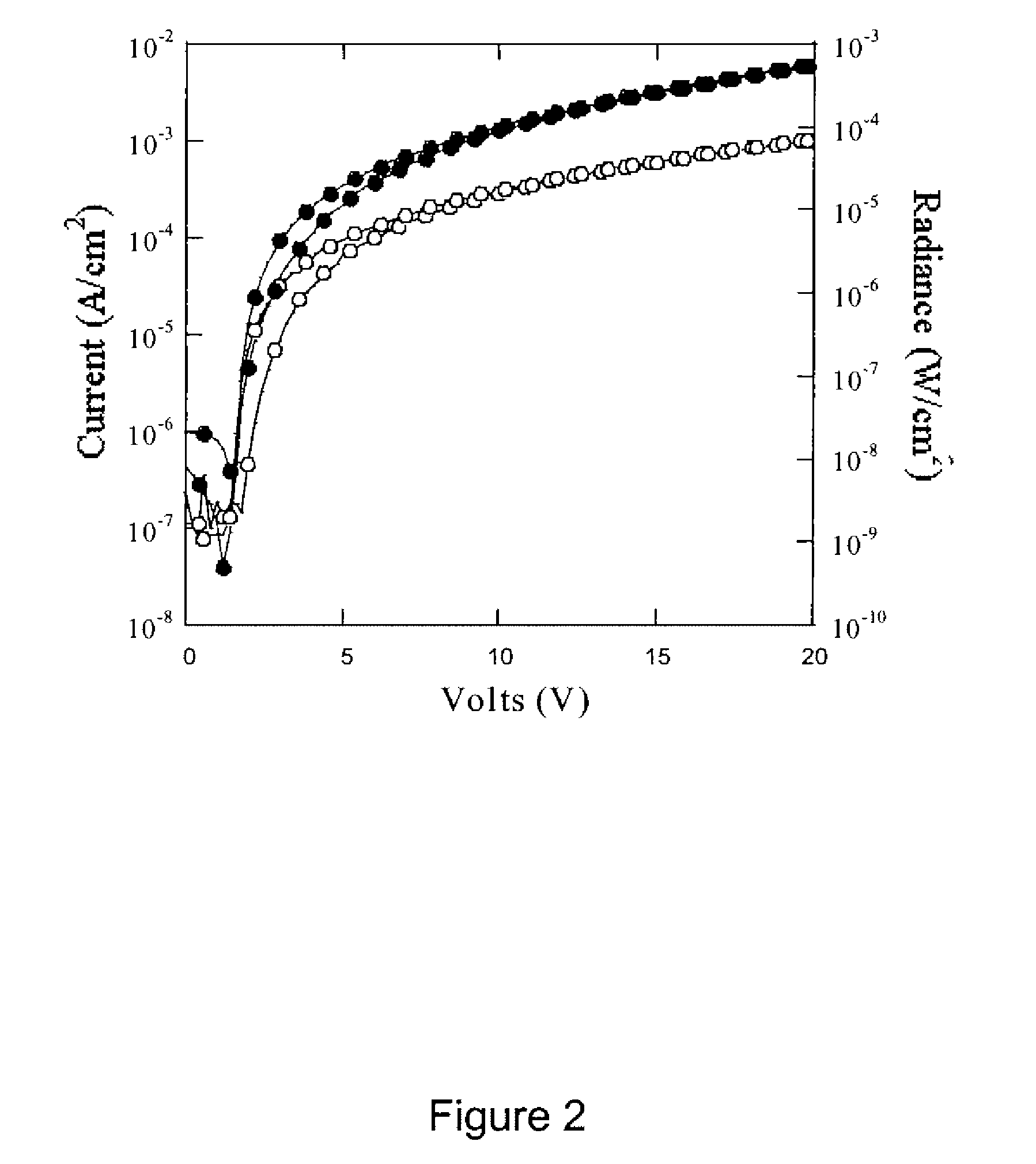
[0009] The addition of a variety of additives to a soluble electroluminescent polymer in solution is used to improve the printability and performance of screen printed light-emitting polymer-based devices. Examples of such additives include transparent and / or charge transporting polymers, gel-retarders, high viscosity liquids, organic and inorganic salts, and oxide nanoparticles. The additives are used to control the viscosity of the electroluminescent polymer ink, to decrease the solvent evaporation rate, and to improve the ink consistency and working time. In addition, these additives can improve the charge injection and power efficiency of light emitting devices manufactured from the screen printable electroluminescent polymer inks.

Problems solved by technology

The small organic molecules however are not printable using a solution-based process.
However, obtaining efficient device operation requires the use of low work-function metals, such as Calcium, that are not stable under atmospheric processing (i.e. printing) conditions.
Nonetheless, the electroluminescent polymer solutions and electrodes mentioned in these patents are not easy applicable to many fully liquid-based manufacturing process, such as screen printing.

Method used


Image

  • Screen Printable Electroluminescent Polymer Ink
  • Screen Printable Electroluminescent Polymer Ink
  • Screen Printable Electroluminescent Polymer Ink

Examples


Embodiment Construction

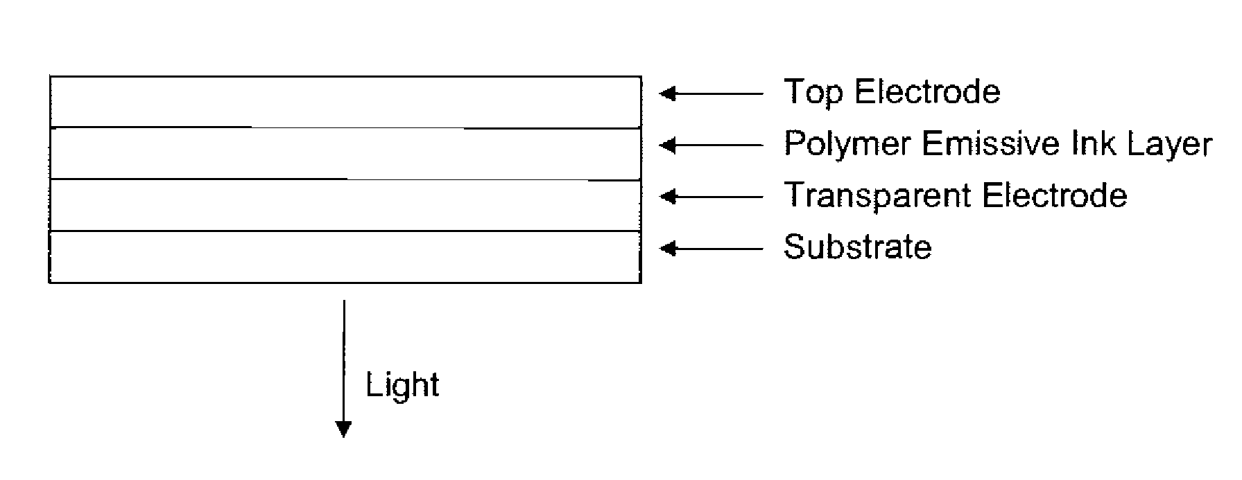
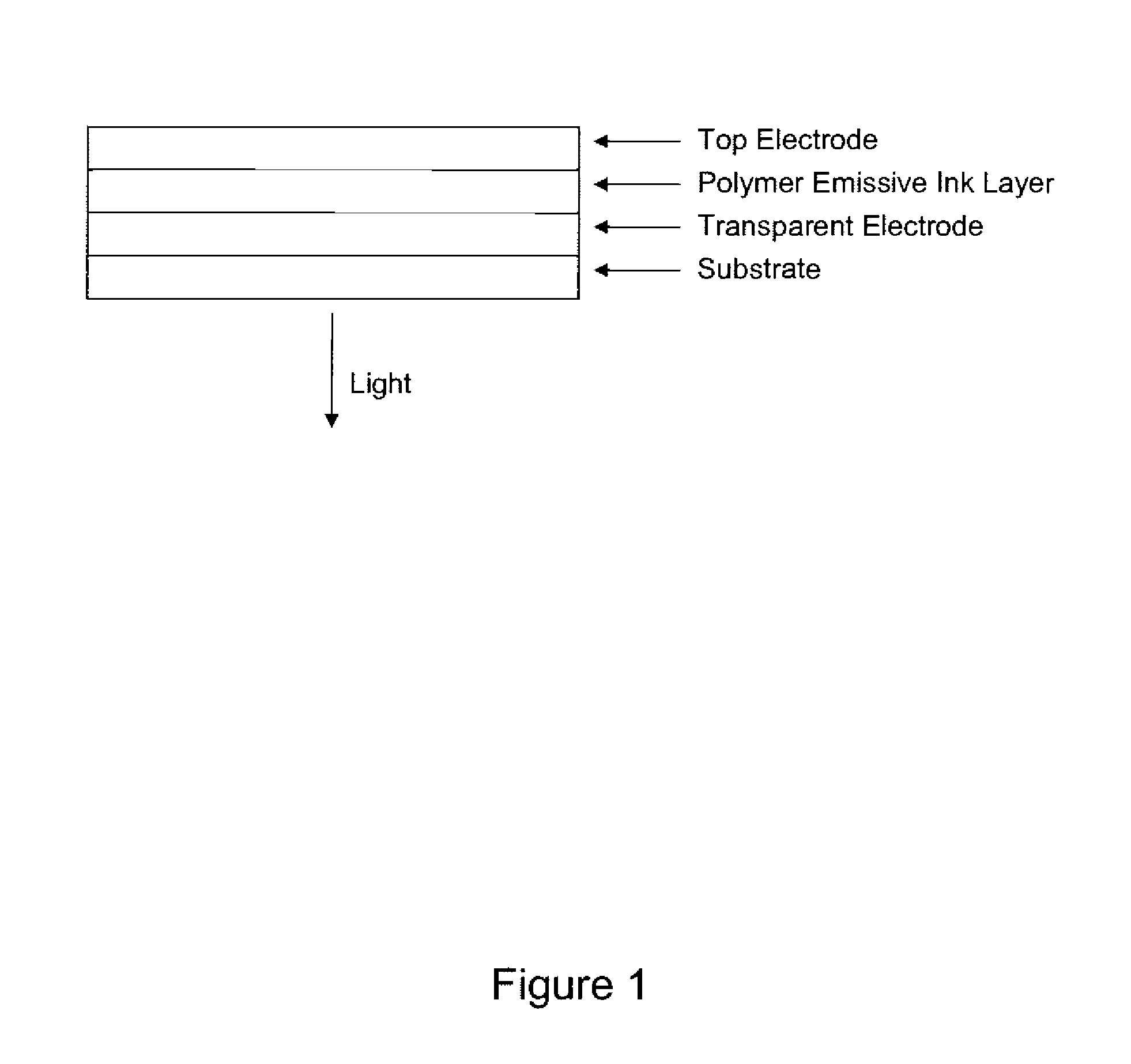
[0013] The present invention will now be described in detail with reference to the drawings, which are provided as illustrative examples of the invention so as to enable those skilled in the art to practice the invention. Notably, the figures and examples below are not meant to limit the scope of the present invention. Moreover, where certain elements of the present invention can be partially or fully implemented using known components, only those portions of such known components that are necessary for an understanding of the present invention will be described, and detailed descriptions of other portions of such known components will be omitted so as not to obscure the invention. Further, the present invention encompasses present and future known equivalents to the known components referred to herein by way of illustration.

[0014] In an embodiment of the present invention, an electroluminescent polymer ink that can be readily screen printed in a manufacturable process has been dev...


PUM

PropertyMeasurementUnit
boiling pointaaaaaaaaaa
viscosityaaaaaaaaaa

Abstract

The addition of a variety of additives to a soluble electroluminescent polymer in solution is used to improve the printability and performance of screen printed light-emitting polymer-based devices. Examples of such additives include transparent polymers, gel-retarders, high viscosity liquids, organic and inorganic salts, and oxide nanoparticles. The additives are used to control the viscosity of the electroluminescent polymer ink, to decrease the solvent evaporation rate, and to improve the ink consistency and working time. In addition, these additives can improve the charge injection and power efficiency of light emitting devices manufactured from the screen printable electroluminescent polymer ink.

Description

PRIORITY CLAIM [0001] This is a divisional of U.S. application Ser. No. 10 / 327,628 filed Dec. 20, 2002 and claims priority benefit from U.S. Provisional Patent Application No. 60 / 342,580 filed Dec. 20, 2001 and entitled “Screen Printable Electroluminescent Polymer Ink”, the contents of which are incorporated herein by reference. CROSS-REFERENCE TO RELATED APPLICATIONS [0002] The present application is related to U.S. application Ser. No. 09 / 844,703, filed Apr. 27, 2001, entitled “Screen Printing Light-Emitting Polymer Pattern Devices”, now U.S. Pat. No. 6,605,483 issued Aug. 12, 2003, which is commonly owned by the present assignee, and the contents of which are incorporated herein by reference.FIELD OF THE INVENTION [0003] The present invention relates to relates to the manufacturing method, namely screen printing, used to produce polymer light emitting devices. More specifically, this invention relates to electrically active polymer-containing compositions and their use in produci...

Claims


Application Information

Patent Timeline
Patent Type & Authority Applications(United States)
IPC IPC(8): H01L51/54C09K11/06C09D11/00C09D11/02H01L51/30H01L51/40H01L51/50
CPCC09D11/50H01L51/0004H01L51/5012H01L51/0038H01L51/0007H10K71/13H10K71/15H10K85/114H10K50/11
Inventor CARTER, SUSAN A.VICTOR, JOHN G.TUTTLE, SARABREEDEN, JANE
Owner CARTER SUSAN A
Learn More