Method and device for regenerating a particle filter in a y-exhaust gas system

a technology of y-exhaust gas and particle filter, which is applied in the direction of mechanical equipment, machines/engines, electric control, etc., can solve the problems of increased exhaust gas counter pressure, clogging of filters with soot, and negative effect on engine performance and fuel consumption, etc., and achieves low application cost and easy retrofit

Inactive Publication Date: 2012-10-18
ROBERT BOSCH GMBH
View PDF6 Cites 14 Cited by
  • Summary
  • Abstract
  • Description
  • Claims
  • Application Information

AI Technical Summary

Benefits of technology

[0030]It may be provided that the particle-filtering components are at least partially combined with an NOx storage catalytic converter, which is typically connected upstream from the particle filter, whereby effective nitrogen oxide retention results in addition to the reduction of particle concentrations.
[0031]The functionality of the method including its variants may be implemented in software as an add-on to a conventional particle filter diagnosis or OBD and / or regeneration strategy within the control unit. The application outlay is therefore low and may be easily retrofitted by a software update. The control unit may be an integral component of a higher-order engine controller (e.g., inside engine control unit ECU).

Problems solved by technology

The soot mass deposited in the filter results in steady clogging of the filter and thus an increase of the exhaust gas counter pressure, however, which has a negative effect on the engine performance and the fuel consumption.
These particle filters clog with soot during operation and must therefore be regenerated at certain time intervals.
This results in the exothermic reaction and therefore in the temperature increase in the catalytic converter.
However, this is equivalent to an NOx breakdown, because the three-way catalytic converter or also the coated particle filter cannot convert NOx in lean operation.

Method used


Image

  • Method and device for regenerating a particle filter in a y-exhaust gas system
  • Method and device for regenerating a particle filter in a y-exhaust gas system
  • Method and device for regenerating a particle filter in a y-exhaust gas system

Examples


Embodiment Construction

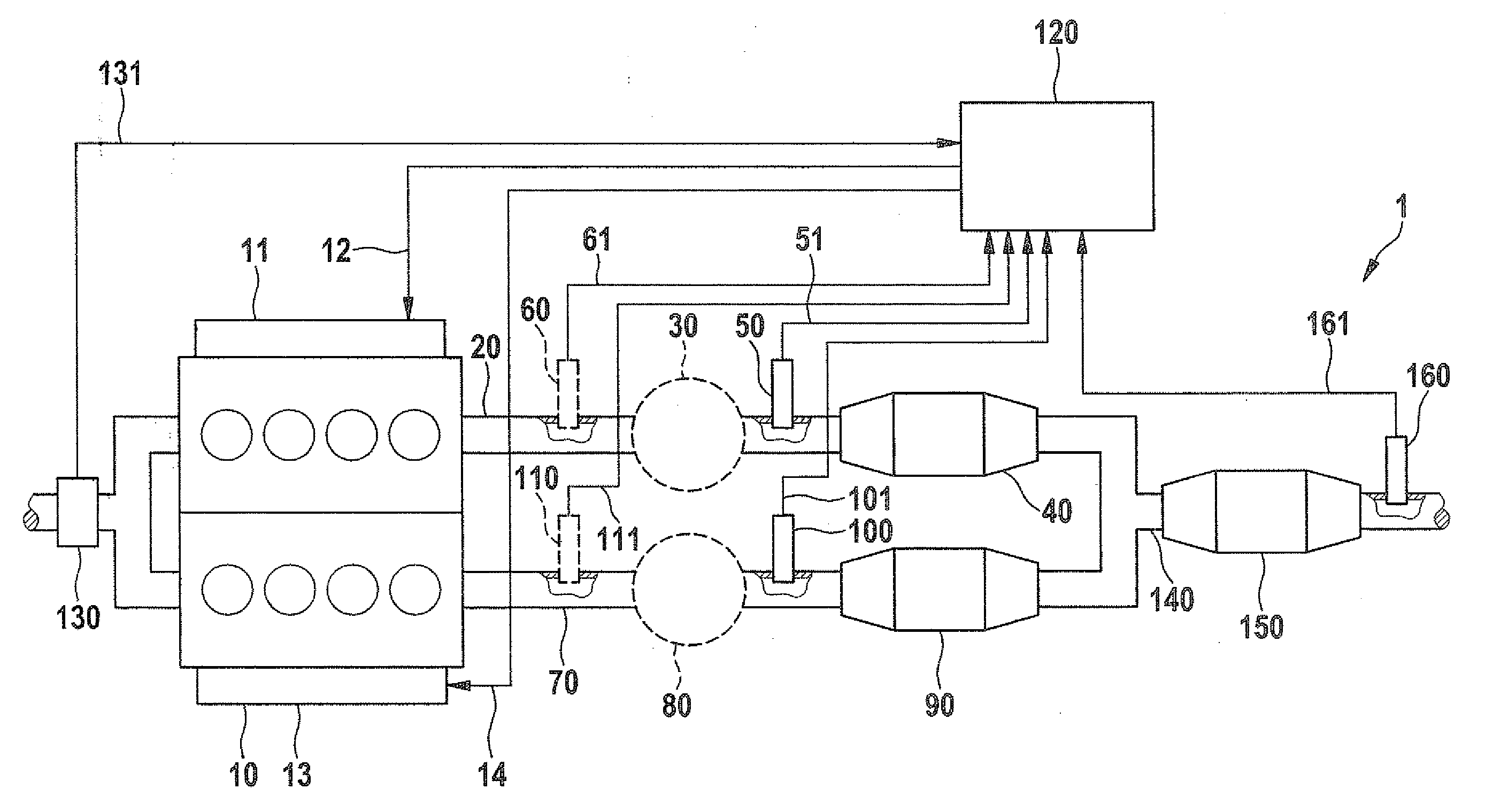
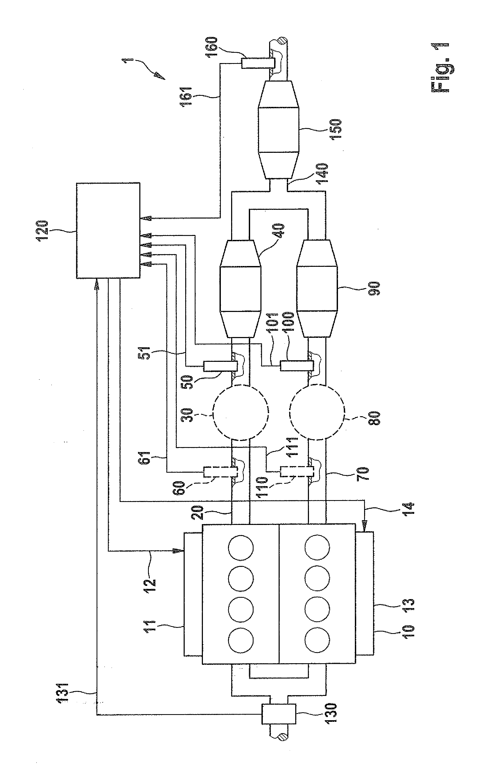
[0037]FIG. 1 shows a schematic view of the technical environment in which the present invention may be used. The main components of an internal combustion engine 1 are shown, which is designed as a bi-turbo eight-cylinder engine, having a twin-pipe exhaust gas system, in the exemplary embodiment, the exhaust gas flows of each 4 cylinders being joined together in one exhaust gas channel (exhaust gas bank).

[0038]An engine block 10, a control unit 120, which cooperates with a control device, and two exhaust gas channels 20, 70, which each have at least one catalytic converter 40, 90, are shown as the main components of internal combustion engine 1. In the example shown, at least one exhaust gas sensor 50, 100, which may be designed as a continuously operating sensor or as a so-called Nernst sensor, is situated in each of the two exhaust gas channels 20, 70 upstream from catalytic converters 40, 90. Exhaust gas sensors 50, 100 are connected with the aid of signal lines 51, 101 to contro...


PUM


Abstract

A method and device for regenerating an exhaust gas aftertreatment component for filtering soot particles in an engine having a first cylinder group, exhaust gases being guided through an exhaust gas channel and whose fuel/air mixture ratio is set via a fuel metering system, activated via a control unit, by a control loop for setting a lambda value using a signal of a first exhaust gas sensor, in the exhaust gas flow direction upstream from a catalytic converter, having at least another cylinder group, exhaust gases being guided through another exhaust gas channel and whose fuel/air mixture ratio is set via another fuel metering system by another control loop for setting another lambda value based on the signal of another exhaust gas sensor, in the exhaust gas flow direction upstream from a catalytic converter, the separate channels joined together downstream to form a shared channel, having a shared catalytic converter.

Description

RELATED APPLICATION INFORMATION[0001]The present application claims priority to and the benefit of German patent application no. 10 2011 007 364.7, which was filed in Germany on Apr. 14, 2011, the disclosure of which is incorporated herein by reference.FIELD OF THE INVENTION[0002]The exemplary embodiments and / or exemplary methods of the present invention relate to a method for regenerating at least one exhaust gas aftertreatment component for filtering soot particles in an internal combustion engine having a first group of cylinders, whose exhaust gases are guided through a first exhaust gas channel, and whose fuel / air mixture ratio is set via a first fuel metering system, activated via a control unit, by a first control loop for setting a first lambda value based on the signal of a first exhaust gas sensor, which is situated upstream from a catalytic converter in the exhaust gas channel in the flow direction of the exhaust gas, and having at least one further group of cylinders, wh...

Claims


Application Information

Patent Timeline
Patent Type & Authority Applications(United States)
IPC IPC(8): F01N3/023F01N3/035
CPCF02D41/025Y02T10/22F02D41/029F02D41/1467F02D2041/1433Y02T10/26F01N3/0814F01N3/101F01N3/105F01N3/2825F01N13/04F01N3/023F01N3/035F01N2470/14F02D41/0275Y02T10/12
Inventor WINKLER, KLAUSZEIN, THOMAS
Owner ROBERT BOSCH GMBH
Why Eureka
Try Eureka