
Ultrasonic transducer for use in a fluid medium

Inactive Publication Date: 2012-10-18
ROBERT BOSCH GMBH
View PDF8 Cites 11 Cited by
  • Summary
  • Abstract
  • Description
  • Claims
  • Application Information

AI Technical Summary

Benefits of technology

[0016]The example ultrasonic transducer and the example method have numerous advantages over conventional ultrasonic transducers and methods. In particular, the stresses in the sealing film illustrated above may be effectively avoided. Deformed films or diaphragms in the area of sonic transducers are conventional, in principle from the area of loudspeaker technology. In this case, however, the diaphragm is usually formed around an active radiation surface in the form of a bead. This area is then itself used as a decoupling suspension. Due to the present invention, on the other hand, both the functions of the suspension of the transducer core and its ultrasonic decoupling are handled by the filled-in decoupling element, while the film is used only for protection against media and is not placed under load due to the deformation during the application of pressure and pressure deformation. The present invention therefore permits a media-resistant ultrasonic transducer to be implemented, which simultaneously includes decoupling of structure-borne noise and is sufficiently stable under pressure and heat for use under harsh conditions, for example in the intake system of a motor vehicle. Both the low pressure side and the supercharged side downstream from a turbocharger or a charge air cooler may be considered as the installation position. As part of an engine controller, the example ultrasonic transducer is suitable for detecting the air mass in gasoline and diesel engines in both passenger cars and commercial vehicles. In commercial vehicles, in particular, the installation position downstream from a charge air cooler is advantageous, this position, however, involving higher pressure and / or media requirements, for example pressure requirements up to 6 bar, a tightness against oil and exhaust gas components and the like. However, these requirements may be effectively met by the example ultrasonic transducer according to the present invention.
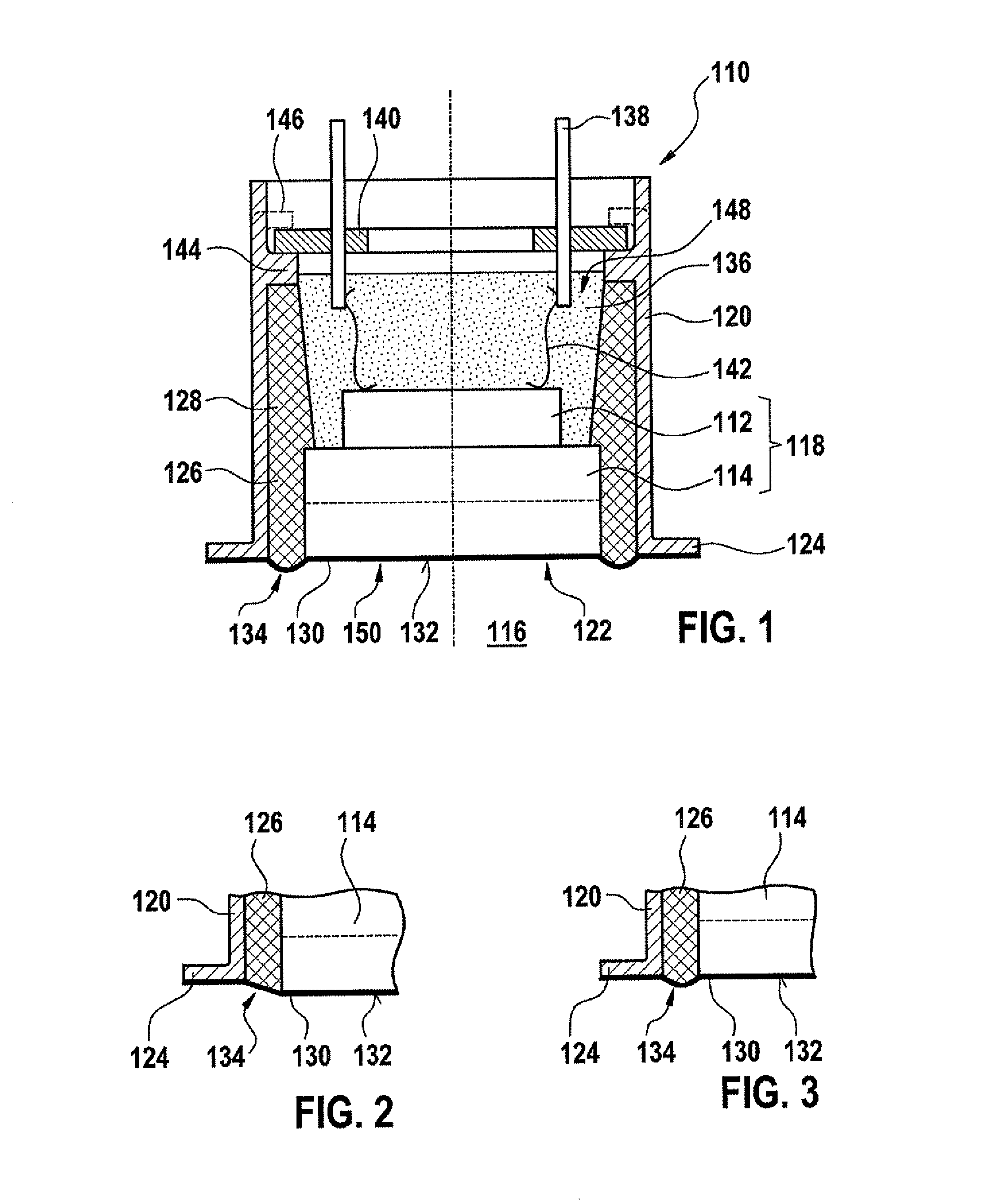
[0017]As illustrated above, the expansion deformation may be designed in different ways without impairing the tightness of the sealing film against pressure and / or media. This sealing film may thus have a reshaped design, that is, a non-flat design, for example according to one or more of the shapes illustrated above. Reshaping the sealing film may thus result, for example, in a type of simplified “bellows,” which permits a relative movement of the transducer core to the housing without placing a load on the sealing film and / or its adhesion. The ultrasonic transducer may thus be subjected to high media, temperature and / or pressure loads, despite the soft, i.e., movable, decoupling. A target conflict between this loadability and an optimum coupling may also be resolved in this way.

Problems solved by technology

In ultrasonic transducers or ultrasonic flowmeters which must meet special pressure requirements, the noise-radiating surface is usually an integral part of a transducer housing or a flow tube, or it is hard-connected to these components, so that it is not usually possible to provide adequate decoupling against the propagation of structure-borne noise.
These compensating movements make it difficult to provide a media-tight transducer design.
In and of themselves, however, these approaches do not usually offer sufficient media resistance for the installation situation, in particular, in motor vehicles.
For example, silicone may swell and / or bleed under the influence of moisture and / or hydrocarbons, and gaps may form between the silicone and the surrounding area.
However, the disadvantage of pure coatings often lies in a poor mechanical cohesion of the coating, in particular under shearing loads, which occur in transition zones between different base materials.
For example, the decoupling material may shift in relation to the impedance matching layer or the transducer housing under mechanical or thermal load, so that the coating may crack on this side.
When using films, in many cases, thermal and mechanical stresses result in at least in an expansion load on the film, so that the film itself or its adhesion is severely stressed.
As described above, a problem arises when using films for sealing purposes, in that thermal and mechanical loads may result in an expansion load which may stress the film itself or its fixing, for example its adhesion to the transducer core and / or the housing.
In this case, the pressure requirements described above, for example, would be difficult to meet.
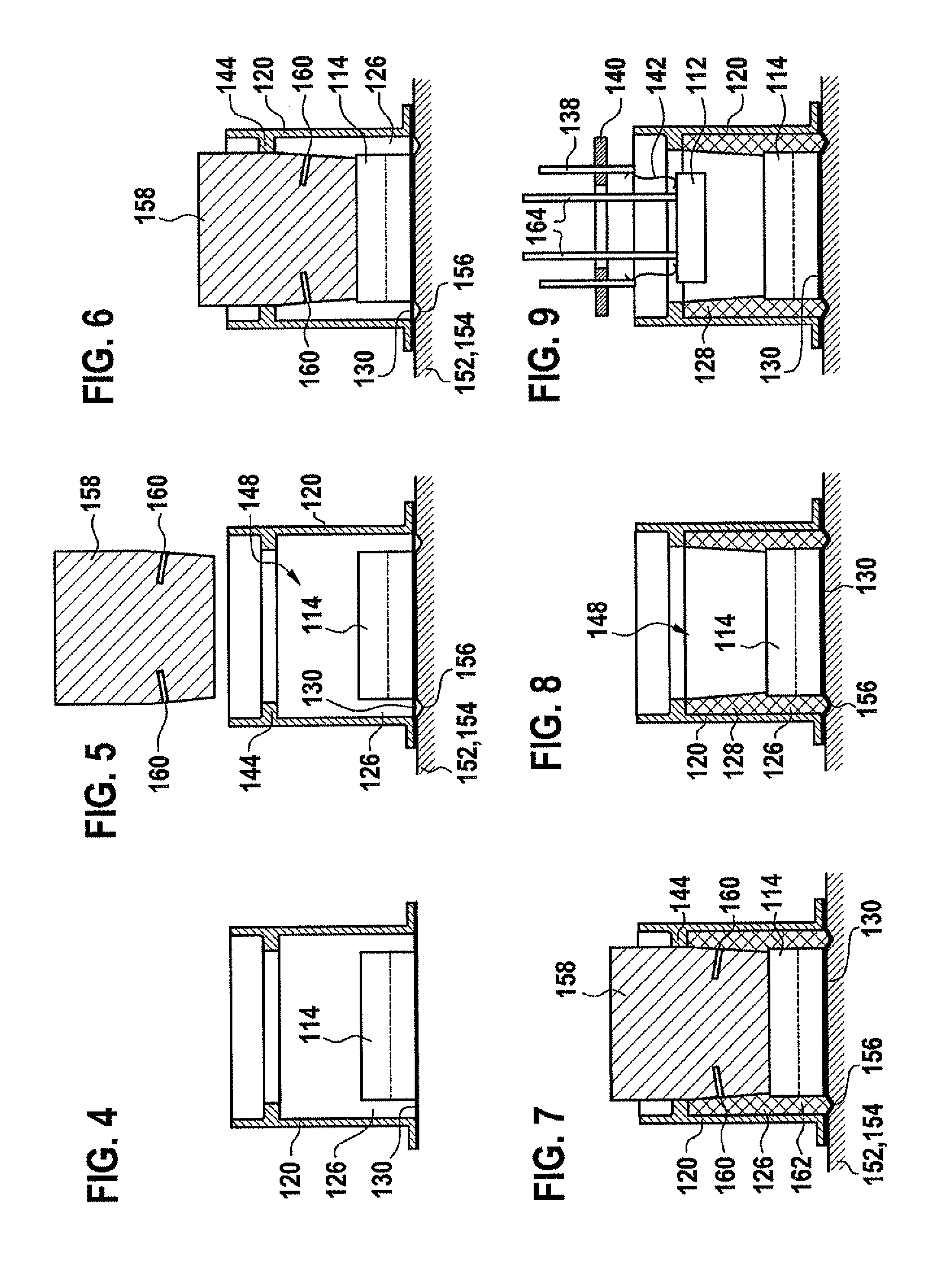
Due to the shaping process of the decoupling element, for example by the LSR process, the deformation itself may already be generated, since this process involves high temperatures and pressures.
This would not be easily possible, for example, in conventional casting processes.
Moreover, a casting process would result in substantially longer curing times, which are uneconomical in a large-scale production.

Method used


Image

  • Ultrasonic transducer for use in a fluid medium
  • Ultrasonic transducer for use in a fluid medium
  • Ultrasonic transducer for use in a fluid medium

Examples


Embodiment Construction

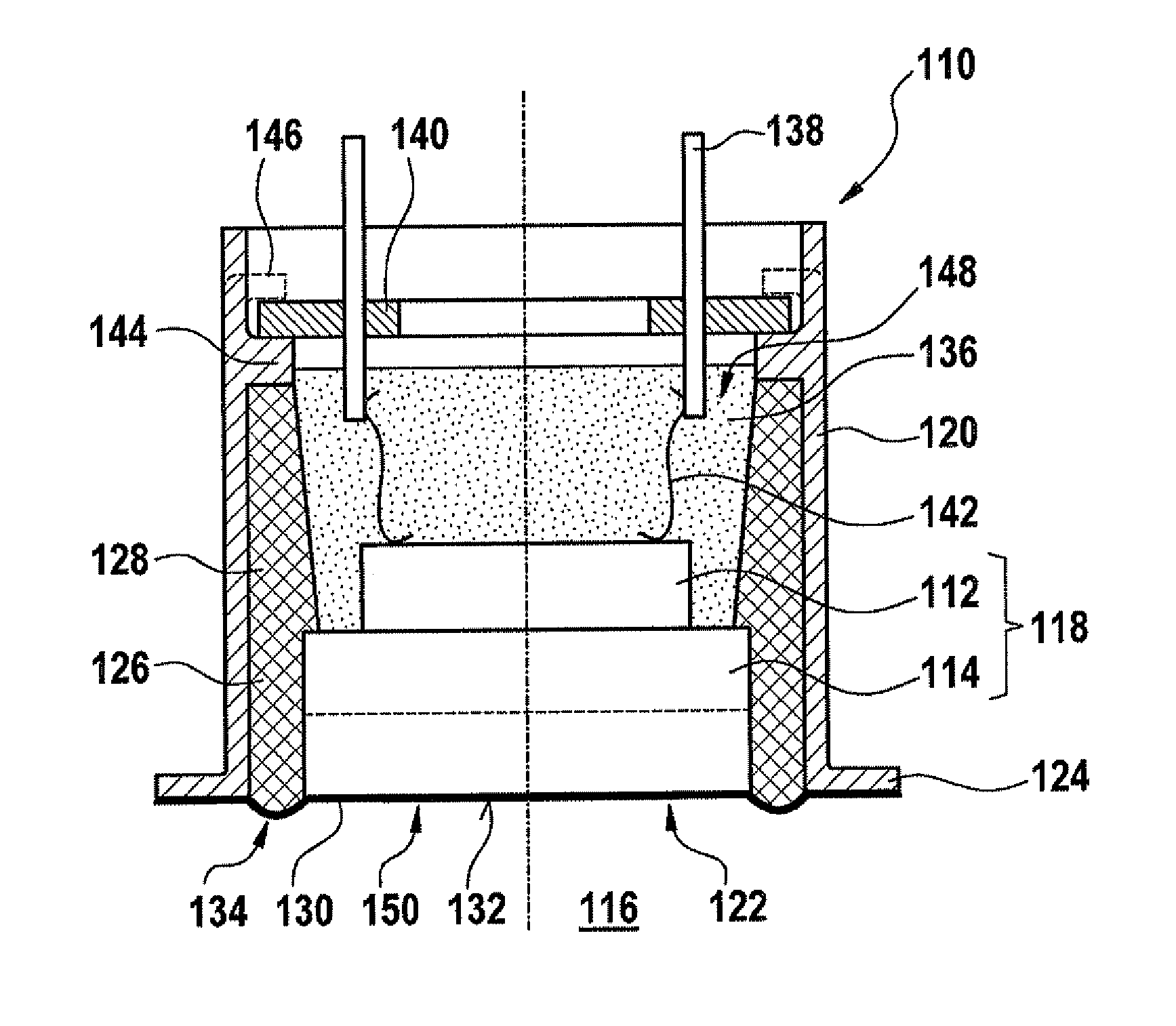
[0027]FIG. 1 shows a sectional representation of an exemplary embodiment of an ultrasonic transducer 110 according to the present invention, viewed from the side. In this exemplary embodiment, the ultrasonic transducer includes an acoustic / electric transducer element 112, for example in the form of a piezoceramic, as well as a matching body 114 situated on the radiation side of acoustic / electric transducer element 112. Matching body 114 is used to improve the acoustic coupling between acoustic / electric transducer element 112 and a fluid medium, which is identified symbolically in FIG. 1 by reference numeral 116. Accordingly, matching body 114 may, for example, at least partially carry out an impedance matching. Reference may be made to German Patent Application Nos. DE 10 2007 010 500 A1 as well as DE 10 2008 055 116.3 and DE 10 2008 055 126.0, which are mentioned above, for embodiments of matching body 114, which may be designed, for example, as a matching layer and which acts as a...


PUM

PropertyMeasurementUnit
Thicknessaaaaaaaaaa
Thicknessaaaaaaaaaa
Areaaaaaaaaaaa

Abstract

An ultrasonic transducer for use in a fluid medium is proposed. The ultrasonic transducer includes at least one transducer core which has at least one acoustic / electric transducer element, in particular a piezoelectric transducer element. The ultrasonic transducer furthermore includes at least one housing, at least one housing opening being at least partially sealed against the fluid medium with the aid of a sealing film which is connected to the transducer core. The sealing film has at least one expansion deformation which is configured to permit a relative movement between the transducer core and the housing.

Description

FIELD OF THE INVENTION[0001]The present invention is directed to ultrasonic transducers which may be used, for example, in ultrasonic flowmeters in process engineering and / or the automotive industry, in particular in the intake system and / or exhaust system of internal combustions engines.BACKGROUND INFORMATION[0002]Ultrasonic transducers of this type are provided for measuring air flows; however, it is also possible, in principle, to use other fluid media, i.e., gases and / or liquids. Examples of ultrasonic transducers are described in German Patent Application No. DE 10 2007 010 500 A1 as well as in the references cited therein. In principle, the ultrasonic transducers described therein may also be modified and / or manufactured according to the present invention within the scope of the present invention. Ultrasonic transducers of the type described are provided, in particular, for measuring air flows, for example to derive an air volume signal within a system controller of an interna...

Claims


Application Information

Patent Timeline
IPC IPC(8): G01F1/66H01L41/22G01R3/00
CPCG01F1/662Y10T29/42G10K11/004G01P5/24G01S7/521G01F23/296G01F23/2968G10K9/13G10K9/22
Inventor MUELLER, ROLANDHUEFTLE, GERHARDHORSTBRINK, MICHAELLANG, TOBIASRADWAN, SAMIKUENZL, BERNDWANJA, ROLAND
Owner ROBERT BOSCH GMBH
Learn More