Solid electrolytic capacitor

a technology of electrolytic capacitors and solids, which is applied in the direction of electrolytic capacitors, fixed capacitor details, fixed capacitors, etc., can solve the problems of failure, coating resin leakage, and difficulty in providing stable fillet formation, and achieve the effect of preventing delamination and stable fillet formation

Active Publication Date: 2012-10-18
TOKIN CORP
View PDF3 Cites 18 Cited by
  • Summary
  • Abstract
  • Description
  • Claims
  • Application Information

AI Technical Summary

Benefits of technology

[0017]In order to solve the abovementioned problem, the present invention provides a solid electrolytic capacitor that enables stable fillet formation at the time of mounting as there is a non-penetrating electrode substrate recessed part in an end part of the electrode substrate and a side surface and an upper part of the electrode substrate recessed part are plated and solder is adhered not on

Problems solved by technology

However, there are problems in the structure with the recesses in the leadframes (as in Japanese Unexamined Patent Application Publication No. 2004-103981) and the structure with the fillet formation part in the electrode substrate (as in Japanese Unexamined Patent Application Publication Nos. 2008-258602 and 2008-270317), thus the inventors have found a problem that it is difficult to provide stable fillet formation while improving the problems.
Further, the outer coating resin will leak to the leadframe mounting terminal surface, and a failure is generated at the time of mounting to the circuit substrate.
However, a part including the fillet is limited to the thickness of the leadframe, and the height for forming the fillet may be insufficient.
However, the electrode substrate projects outside the outer coating resin, and the size of the outer coating resin is limited.
Therefore, the cathode area is reduced and thereby generating a disadvantageous structure for capacity increase.
This is because t

Method used


Image

  • Solid electrolytic capacitor
  • Solid electrolytic capacitor
  • Solid electrolytic capacitor

Examples


first exemplary embodiment

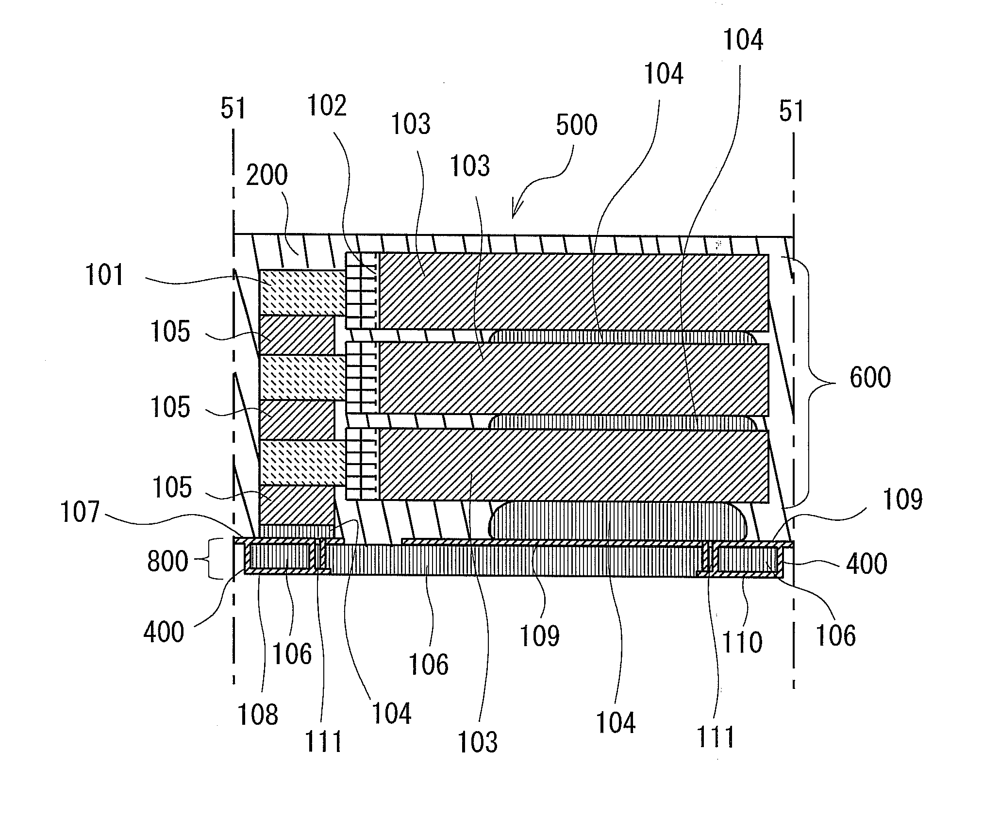
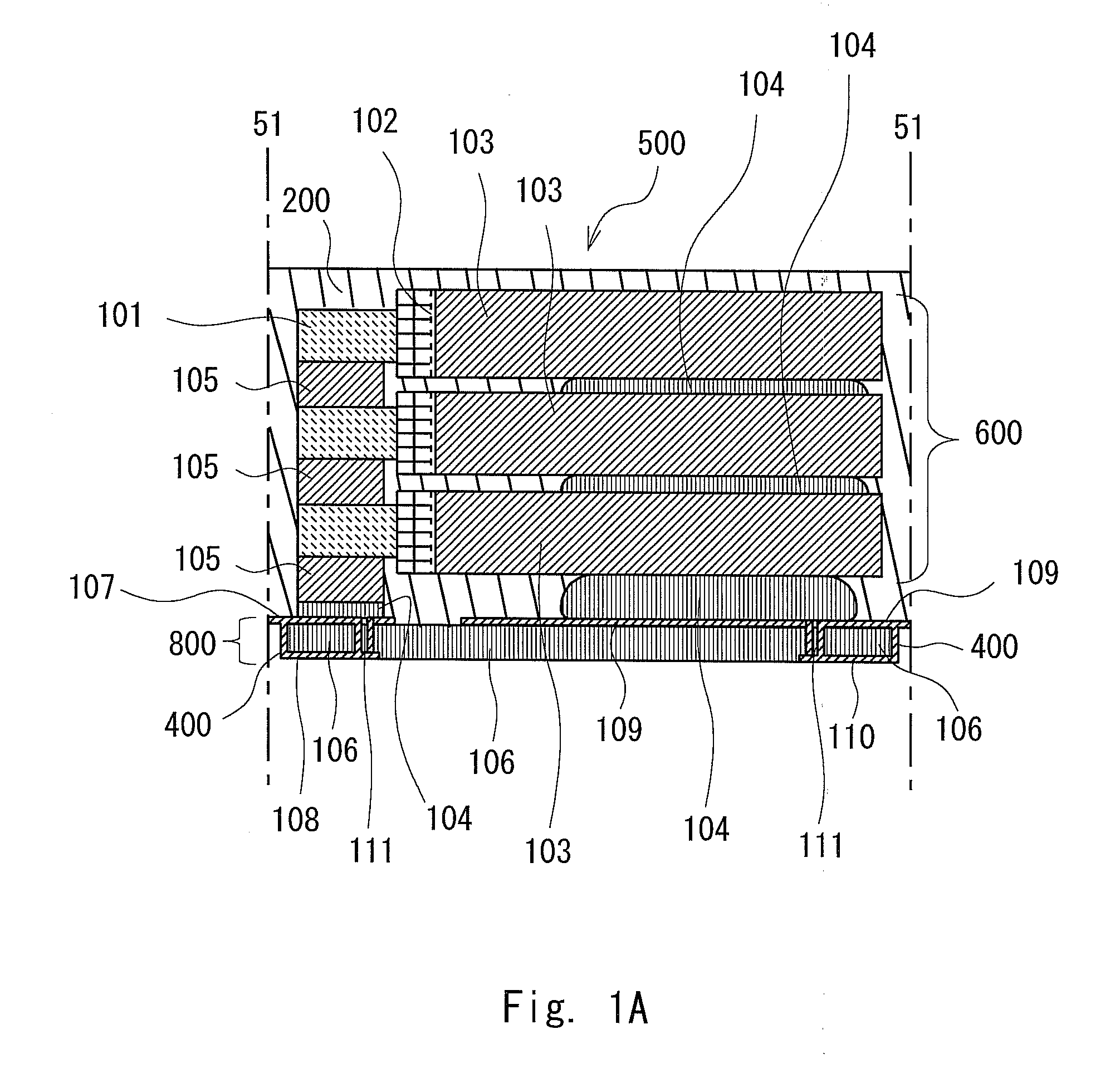
[0040]A first embodiment is explained using FIGS. 1A to 1D and FIGS. 5A and 5B.

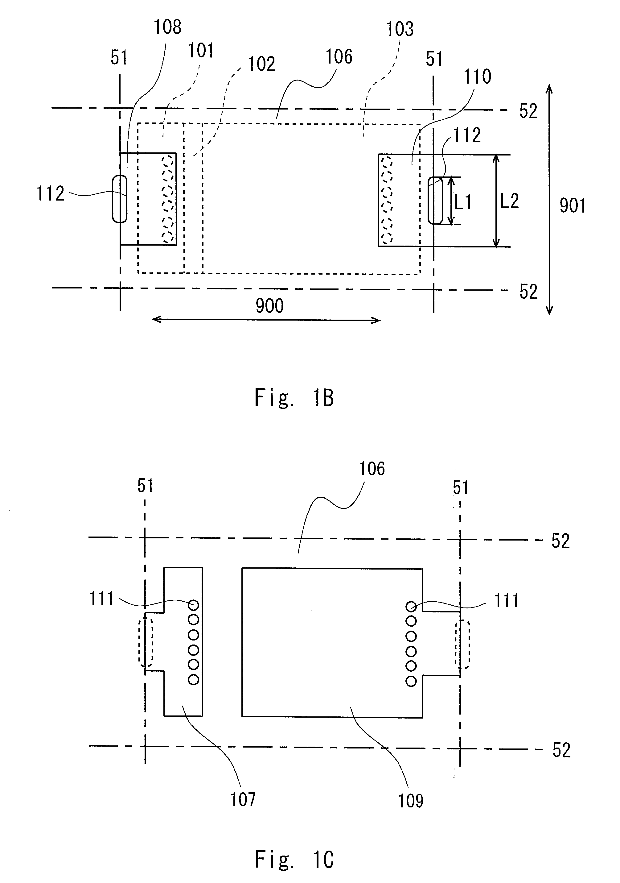
[0041]FIGS. 1A to 1D are views showing a solid electrolytic capacitor according to the first embodiment of the present invention. FIG. 1A is a cross-sectional diagram of one solid electrolytic capacitor. FIG. 1B is a product bottom view viewed from a mounting electrode side. FIG. 1C is a top view viewed from an electrode terminal for element connection side. FIG. 1D is an enlarged diagram of a code 112 part of FIG. 1B.

[0042]A solid electrolytic capacitor 500 can be obtained by the manufacture as described below. First, a capacitor element is manufactured. The capacitor element includes one capacitor element anode part (anode part) 101 of an anode body including a linear, foil-like, or plate-like valve metal and a capacitor element cathode part (cathode part) 103 including a dielectric layer, a solid electrolyte layer, a graphite layer, and a silver paste layer, which are sequentially formed to the other s...

second exemplary embodiment

[0059]A second embodiment is explained using FIGS. 2A to 2C.

[0060]FIGS. 2A to 2C show the configuration of a solid electrolytic capacitor according to the second embodiment of the present invention. FIG. 2A is a cross-sectional diagram of one solid electrolytic capacitor. FIG. 2B is a product bottom view viewed from the mounting electrode side. FIG. 2C is a top view viewed from the electrode for element connection.

[0061]As the manufacture of the capacitor stack element 600 is same as the first embodiment, the explanation is omitted here. As shown in FIG. 2A, there are three terminals of the mounting electrode in the electrode substrate 800 of this embodiment.

[0062]That is, a second cathode terminal 110b of the mounting electrode side is placed at a position spaced with an interval R in the first direction 900 from a first cathode terminal 110a of the mounting electrode side (which is mounting electrode side cathode terminal 110 of the first embodiment). This second cathode terminal ...

third embodiment

[0069]A third embodiment is explained using FIGS. 3A and 3B.

[0070]FIG. 3A is a product bottom view viewed from the mounting electrode side. FIG. 3B is a top view viewed from the electrode for element connection.

[0071]As compared with the second embodiment, in the third embodiment, there is no recessed parts 112c and 112d, and although the second cathode terminal 110b and the cathode terminal for element connection 109 extend in the second direction 901 but not up to the cutout line 52 and stops before the cutout line 52.

[0072]Other configuration is the same as the second embodiment. Note that there is no difference observed in the ESL value between the second and the third embodiments.


PUM


Abstract

Provided is a solid electrolytic capacitor that is excellent in productivity, has improved volumetric efficiency aiming for capacity increase, a stable fillet shape when mounted, and has excellent ESL characteristics. Included is a capacitor stack element composed of a stack of capacitor elements. The capacitor element includes one anode part of an anode body made of linear, foil-like, or plate-like valve metal and a cathode part composed of dielectric, solid electrolyte, graphite, and silver paste layers, which are sequentially formed to another surface of the anode body separated by insulating resin. A fillet formation part with a recessed part is provided to an end surface of anode and cathode terminals of a mounting electrode side of a first direction end surface of the electrode substrate to which the capacitor stack element is mounted. Further, the anode and cathode terminals for element connection reach the end surface of the first direction.

Description

BACKGROUND OF THE INVENTION[0001]1. Field of the Invention[0002]The present invention relates to a solid electrolytic capacitor used for a power supply circuit etc.[0003]2. Description of Related Art[0004]There has been a solid electrolytic capacitor using tantalum, niobium, or the like as a valve metal. Such a solid electrolytic capacitor is small, has a large capacitance, excellent frequency characteristics, and low ESL (equivalent series inductance) characteristics and is widely used for a decoupling circuit, a power supply circuit or the like of a CPU (Central Processing Unit).[0005]Commercial production of the solid electrolytic capacitor of especially a substrate electrode structure type is progressing with development of a portable electronic device. When this kind of solid electrolytic capacitor is mounted on an electronic circuit board, the structure of a connection part between a terminal part and a mounting board which is called a solder fillet becomes important along wit...

Claims


Application Information

Patent Timeline
IPC IPC(8): H01G9/15H01G9/04
CPCH01G9/04H01G9/012H01G9/042H01G9/15H01G9/26
Inventor KAWAI, AKIHIROARAKI, KENJI
Owner TOKIN CORP
Why Eureka
Try Eureka