

Multichannel nonlinearity compensation in an optical communications link
- Summary
- Abstract
- Description
- Claims
- Application Information
AI Technical Summary
Benefits of technology
Problems solved by technology
Method used
Image

Examples
embodiment 104
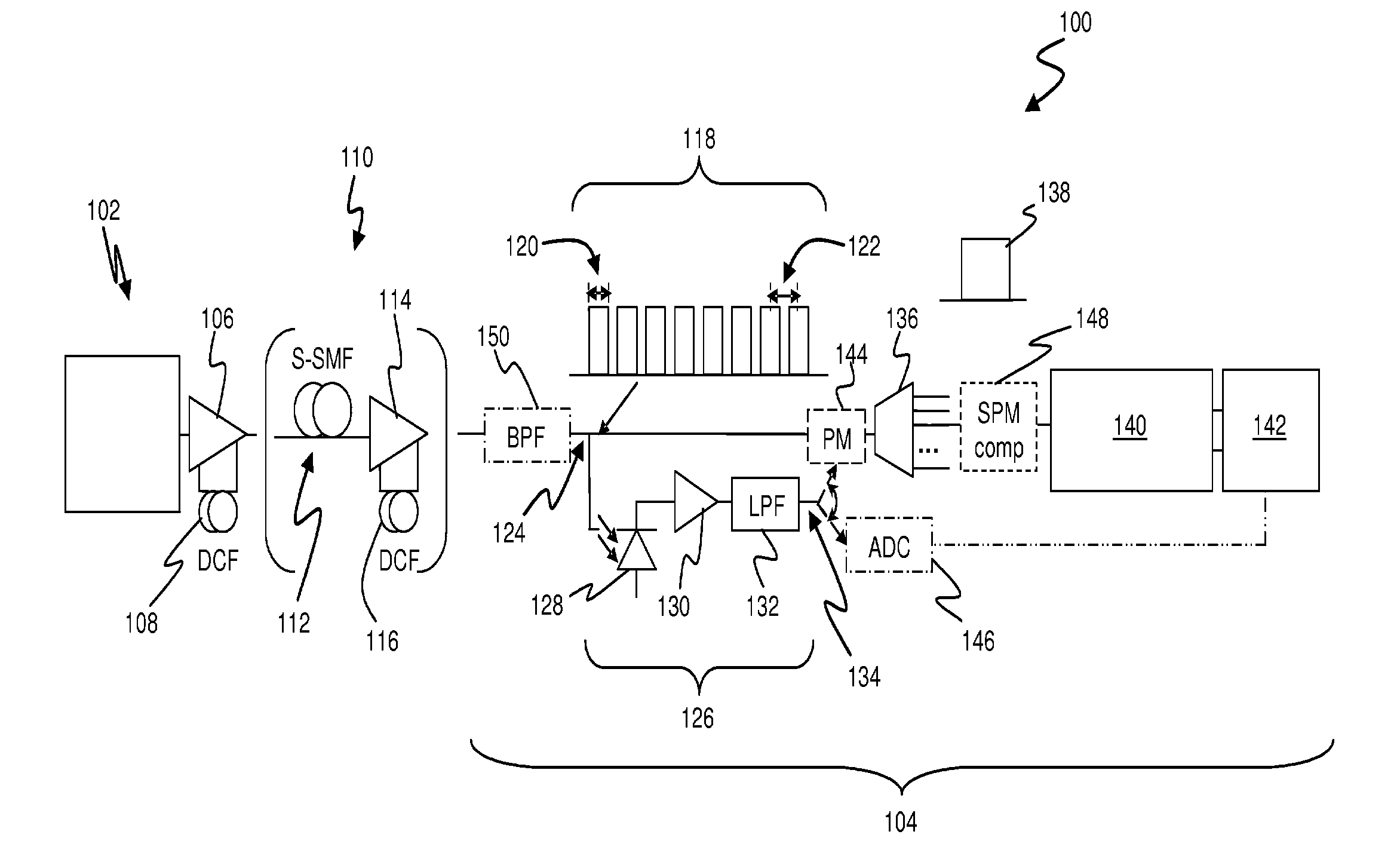
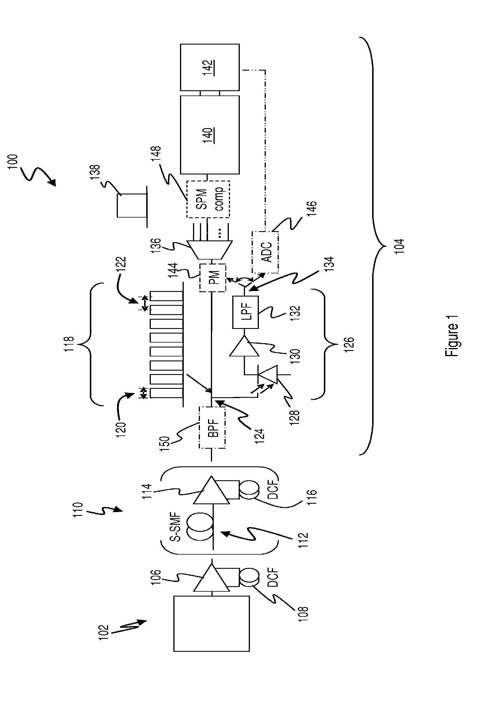
[0045]It should be noted that at least in embodiments of the invention employing an optical phase modulator 144, nonlinear compensation may be performed without detection and / or processing of individual optical signals. It will therefore be appreciated that while an embodiment 104 is presently described in which nonlinear compensation is performed at a receiving end of an optical transmission link, it is also possible to perform inline compensation at one or more points within an optical link or network, such as at amplifier locations or add / drop nodes.
[0046]Preferably, the receiving apparatus 104 also incorporates compensation for single-channel nonlinear effects, such as self-phase modulation (SPM). An SPM compensation block 148 is illustrated in the schematic diagram of FIG. 1, the operation of which may be in accordance with the principles described in U.S. patent application Ser. No. 12 / 445,386 (also published as International Publication No. WO 2008 / 074085). This prior applica...
embodiment 100
[0048]Furthermore, it may be desirable that the frequency response of the band-pass filter (or WDM demultiplexer) 150 include a gradual “roll off” at each edge of the frequency band, such that only a proportion of power in those channels most distantly spaced (in wavelength) from the received signal of interest is directed to the first receiver 126. In this way, the contribution of more-distant channels to the control signals produced at the output 134 of the receiver 126 may be commensurate with the contribution of those channels to cross-channel nonlinear distortion of the optical signal of interest. In the embodiment 100, the band-pass filter 150 is disposed prior to the optical tap 124, however in alternative embodiments it may be disposed between the optical tap 124 and the receiver 126, such that the transmitted WDM optical signals reaching the WDM demultiplexer 136 are unaffected by the characteristics of the band-pass filter 150.
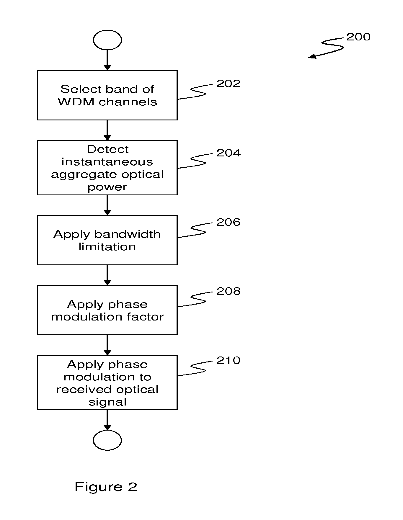
[0049]Turning now to FIG. 2, there is shown a ...
PUM
 Abstract
Description
Claims
Application Information