Method for manufacturing a work piece by vacuum assisted resin transfer moulding

a technology of vacuum assisted resin and manufacturing method, which is applied in the manufacture of final products, machines/engines, weaving, etc., can solve the problems of inherited expensive textile machinery used in weaving fabrication, and achieve the effect of reducing the cost of work pieces

Inactive Publication Date: 2012-10-18
SIEMENS AG
View PDF30 Cites 8 Cited by
  • Summary
  • Abstract
  • Description
  • Claims
  • Application Information

AI Technical Summary

Benefits of technology

[0023]The inventive work piece is manufactured by the previously described inventive method. The work piece may especially be a wind turbine rotor blade. Generally, the inventive work piece has the same advantages as the previously described method. For instance, in the inventive work piece resin rich areas or resin rich pockets are reduced and the work piece can be manufactured at reduced costs.

Problems solved by technology

Special stitching patterns have been introduced, in order to reduce the resin rich pockets in the laminate, but the limitations have always been the inherited expensive textile machinery used in the weaving fabrication.

Method used


Image

  • Method for manufacturing a work piece by vacuum assisted resin transfer moulding
  • Method for manufacturing a work piece by vacuum assisted resin transfer moulding
  • Method for manufacturing a work piece by vacuum assisted resin transfer moulding

Examples


Embodiment Construction

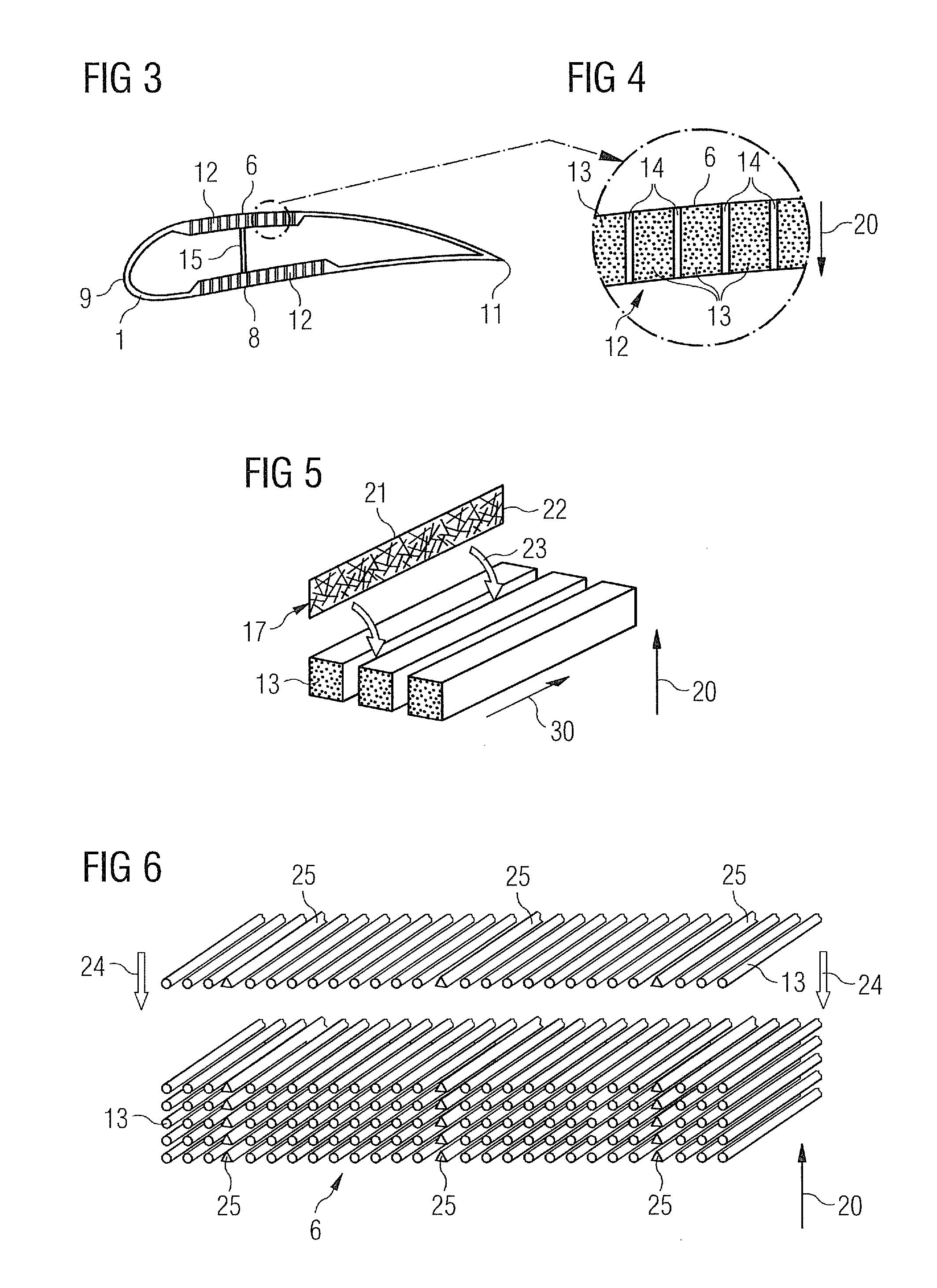
[0034]Embodiments of the present invention will now be described with reference to FIGS. 1 to 9.

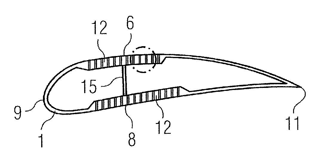
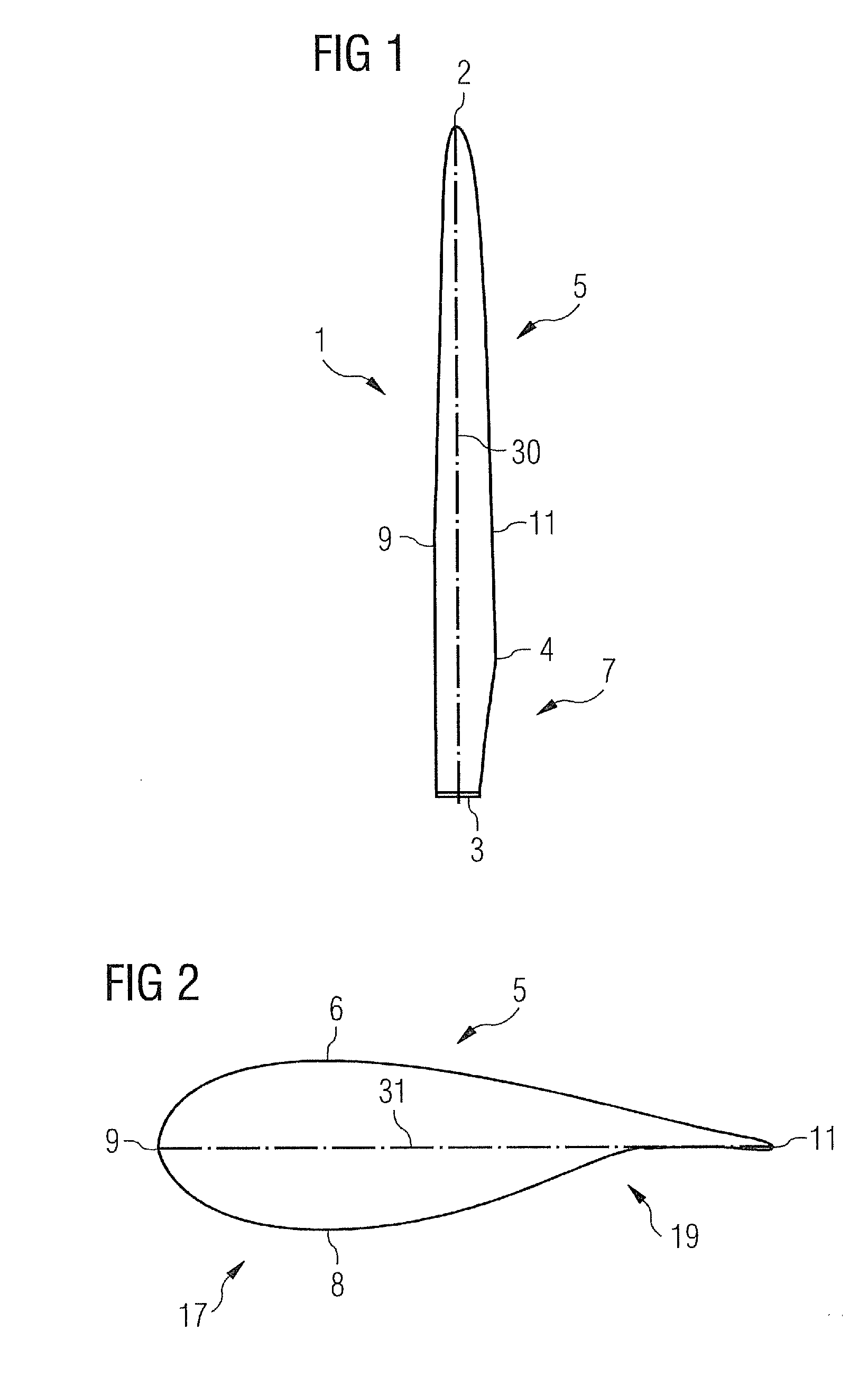
[0035]FIG. 1 shows a rotor blade in a plan view on the plane defined by the blade's span and the blade's chord. The span direction is indicated by reference numeral 30. The rotor blade 1 shown in FIG. 1 comprises a root portion 3 with a cylindrical profile and a tip 2. The tip forms the outermost part of the blade. The cylindrical profile of the root portion 3 serves to fix the blade to a bearing of a rotor hub. The rotor blade 1 further comprises a so-called shoulder 4 which is defined as the location of its maximum profile depth, i.e. the maximum chord length of the blade. Between the shoulder 4 and the tip 2 an airfoil portion 5 extends which has an aerodynamically shaped profile. Between the shoulder 4 and the cylindrical root portion 3, a transition portion 7 extends in which a transition takes place from the aerodynamic profile of the airfoil portion 5 to the cylindrical profile of ...


PUM

PropertyMeasurementUnit
distancesaaaaaaaaaa
sizeaaaaaaaaaa
stiffnessaaaaaaaaaa

Abstract

A method for manufacturing a work piece by Vacuum Assisted Resin Transfer Moulding is includes the steps of placing fibre rovings in a mould of a closed mould system which comprises a mould cavity, placing at least one resin distribution device between the fibre rovings, and applying vacuum to the closed mould system and injecting resin into the mould cavity.

Description

CROSS REFERENCE TO RELATED APPLICATIONS[0001]This application claims priority of European Patent Office application No. 11162406.0 EP filed Apr. 14, 2011. All of the applications are incorporated by reference herein in their entirety.FIELD OF INVENTION[0002]The present invention relates to a method for manufacturing a work piece by vacuum assisted resin transfer moulding, especially to a method for manufacturing a wind turbine rotor blade. It further relates to a work piece, for example, a wind turbine rotor blade.BACKGROUND OF INVENTION[0003]Fibre reinforced plastic composites are used in a variety of technical products such as cars, wind turbine blades, storage tanks etc. Most products of big size, such as wind turbine blades are manufactured by placing woven glass fabric, delivered on rolls, into one or more moulds. In the common resin injection process known as VARTM (vacuum assisted resin transfer moulding), the moulds are closed, and vacuum is applied to the closed mould syste...

Claims


Application Information

Patent Timeline
Patent Type & Authority Applications(United States)
IPC IPC(8): F03D1/06B32B5/08B29C45/02
CPCB29C70/48B29C70/547B29L2031/085Y02E10/721B29L2031/082Y10T428/249922Y02E10/72Y02P70/50
Inventor GROVE-NIELSEN, ERIK
Owner SIEMENS AG
Why Eureka
Try Eureka