
Film formation apparatus for semiconductor process and method for using the same

a technology of film formation apparatus and semiconductor device, which is applied in the direction of coating, coating, chemical vapor deposition coating, etc., can solve the problems of reducing the yield of semiconductor device to be manufactured, deteriorating some components of processing apparatus, and peeling of some by-product films, etc., to achieve the effect of not lowering the productivity

Active Publication Date: 2012-10-18
TOKYO ELECTRON LTD
View PDF12 Cites 3 Cited by
  • Summary
  • Abstract
  • Description
  • Claims
  • Application Information

AI Technical Summary

Benefits of technology

The present invention provides a film formation apparatus for a semiconductor process that can prevent particle generation without lowering productivity. The apparatus includes a process container, a heater, an exhaust system, a film formation gas supply circuit, an oxidizing gas supply circuit, a mechanism for loading and unloading a target substrate, and a control section for executing a method that includes performing a film formation process to form a silicon nitride film on the target substrate, unloading the substrate, and supplying an oxidizing gas into the process container to perform an oxidation process on by-product films deposited on the inner surface of the process container. This method ensures that the by-product films are changed into a composition richer in oxygen than nitrogen at a specific depth, resulting in improved quality of the film formed.

Problems solved by technology

If the film formation process is continued while by-product films are present on the inner surface of the process container, a stress is generated and causes peeling of some of the by-product films and the quartz of the process container due to a difference in coefficient of thermal expansion between the quartz and by-product films.
Consequently, particles are generated, and may decrease the yield of semiconductor devices to be fabricated and / or deteriorate some components of the processing apparatus.
However, in this case, the downtime of the heat processing apparatus becomes larger and thereby deteriorates productivity.

Method used


Image

  • Film formation apparatus for semiconductor process and method for using the same
  • Film formation apparatus for semiconductor process and method for using the same
  • Film formation apparatus for semiconductor process and method for using the same

Examples


Embodiment Construction

[0023]Embodiments of the present invention will now be described with reference to the accompanying drawings. In the following description, the constituent elements having substantially the same function and arrangement are denoted by the same reference numerals, and a repetitive description will be made only when necessary.

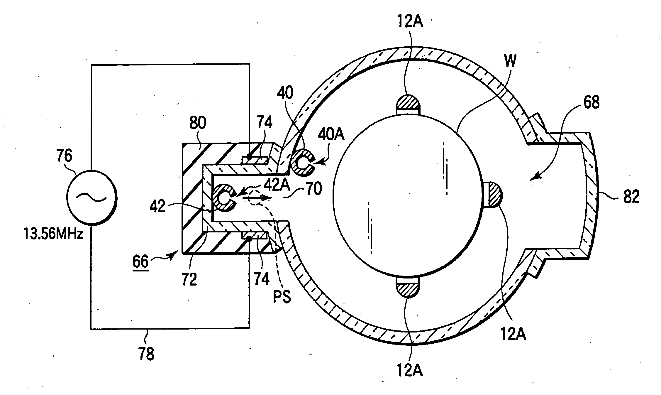
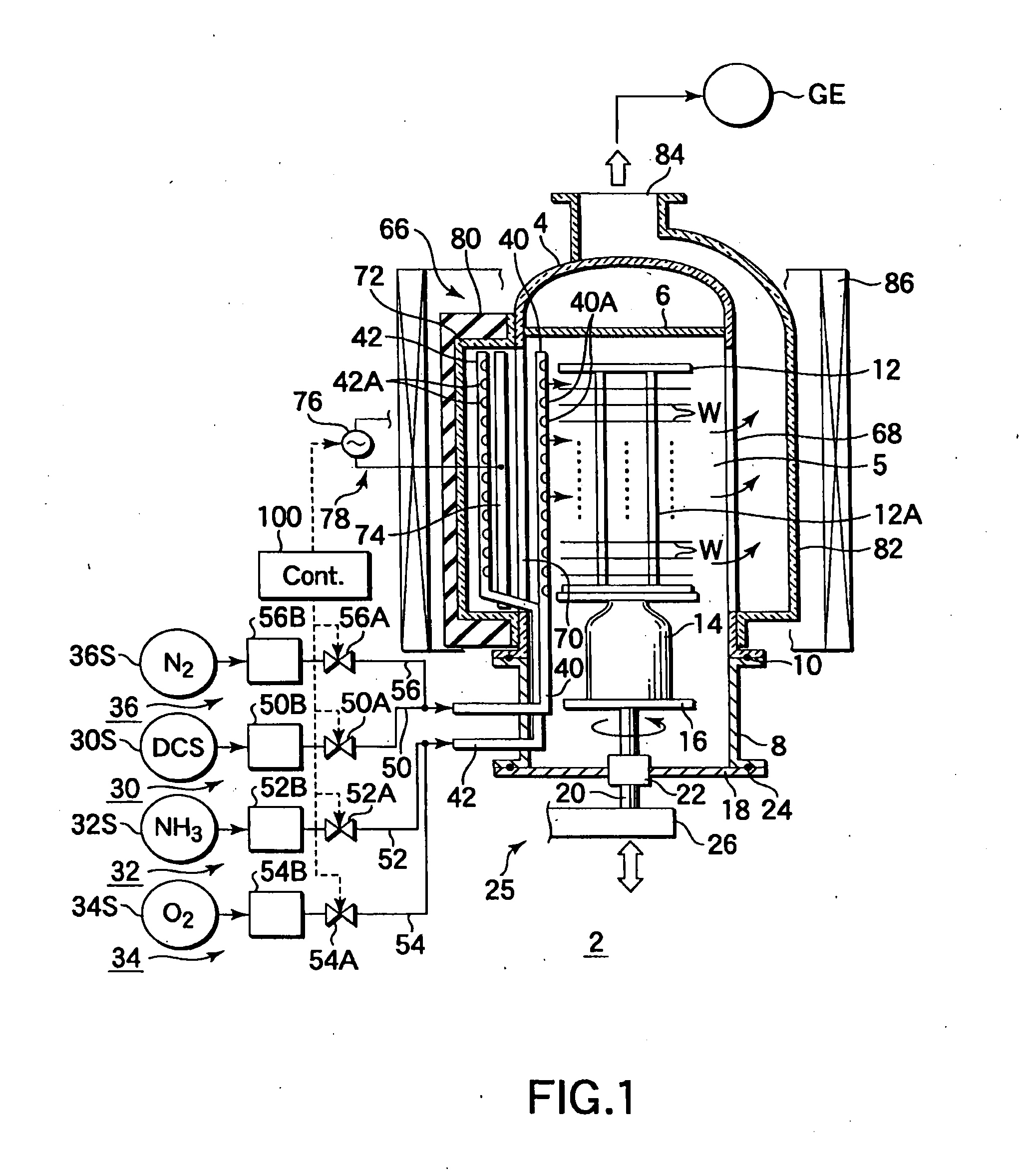
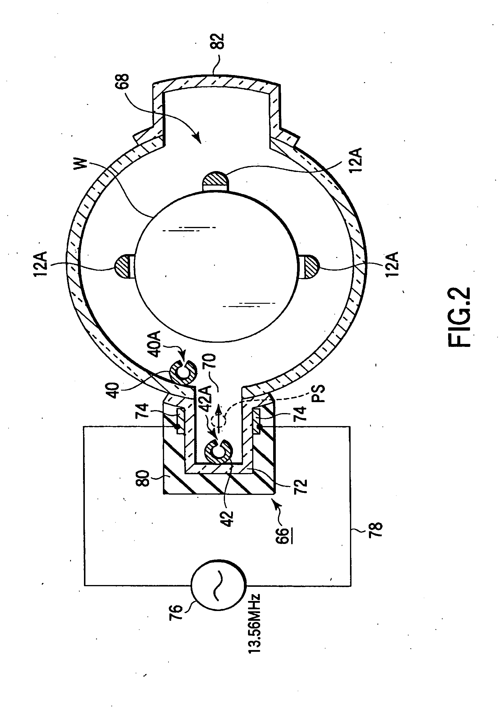
[0024]FIG. 1 is a sectional view showing a film formation apparatus (vertical CVD apparatus) according to an embodiment of the present invention. FIG. 2 is a sectional plan view showing part of the apparatus shown in FIG. 1. The film formation apparatus 2 has a process field configured to be selectively supplied with a first process gas comprising dichlorosilane (DCS: SiH2Cl2) gas as a silicon source gas, a second process gas comprising ammonia (NH3) gas as a nitriding gas, and a third process gas comprising oxygen (O2) gas as an oxidizing gas for an auxiliary process. The film formation apparatus 2 is configured to form a silicon nitride film on target substrate...


PUM

PropertyMeasurementUnit
thicknessaaaaaaaaaa
thicknessaaaaaaaaaa
depthaaaaaaaaaa

Abstract

A method is provided for using a film formation apparatus including a process container having an inner surface, which contains as a main component a material selected from the group consisting of quartz and silicon carbide. The method includes performing a film formation process to form a silicon nitride film on a product target substrate inside the process container, and then, unloading the product target substrate from the process container. Thereafter, the method includes supplying an oxidizing gas into the process container with no product target substrate accommodated therein, thereby performing an oxidation process to change by-product films deposited on the inner surface of the process container into a composition richer in oxygen than nitrogen, at a part of the by-product films from a surface thereof to a predetermined depth.

Description

CROSS-REFERENCE TO RELATED APPLICATIONS[0001]The present application is a divisional of U.S. application Ser. No. 11 / 987,108, filed on Nov. 27, 2007, the entire contents of which is incorporated herein by reference. U.S. application Ser. No. 11 / 987,108 claims the benefit of priority under 35 U.S.C. 119 from Japanese Application No. 2006-323805 filed Nov. 30, 2006.BACKGROUND OF THE INVENTION[0002]1. Field of the Invention[0003]The present invention relates to a film formation apparatus for a semiconductor process for forming a silicon nitride film on a target substrate, such as a semiconductor wafer, and also to a method for using the apparatus. The term “semiconductor process” used herein includes various kinds of processes which are performed to manufacture a semiconductor device or a structure having wiring layers, electrodes, and the like to be connected to a semiconductor device, on a target substrate, such as a semiconductor wafer or a glass substrate used for an FPD (Flat Pane...

Claims


Application Information

Patent Timeline
Patent Type & Authority Applications(United States)
IPC IPC(8): C23C16/34C23C16/50C23C16/52
CPCC23C16/345C23C16/45525C23C16/45527H01J37/32862C23C16/45546C23C16/507C23C16/4554C23C16/4404C23C16/505
Inventor MATSUURA, HIROYUKI
Owner TOKYO ELECTRON LTD
Learn More