Miniature toroidal radio frequency ion trap mass analyzer

a radio frequency ion trap and mass analyzer technology, applied in the field of storage, separation and analysis of ions, can solve the problems of large reduction of operating voltage, inability to analyze mass, so as to achieve easy interface and reduce dimensions

Active Publication Date: 2012-10-25
BRIGHAM YOUNG UNIV
View PDF8 Cites 14 Cited by
  • Summary
  • Abstract
  • Description
  • Claims
  • Application Information

AI Technical Summary

Benefits of technology

[0013]In a first embodiment, the present invention is approximately a ⅕ scale version of a toroidal radio frequency (RF) ion trap mass analyzer operating with RF trapping voltages less than ca. 1 kVp-p yet despite the reduced dimensions, retains roughly the same ion trapping volume as conventional 3D quadrupole ion traps, wherein the curved geometry enables construction of a compact mass analyzer and easy interface with conventional electron multipliers.

Problems solved by technology

For example, IT analyzers are inherently small, even as implemented commercially.
Furthermore, because the radio frequency (RF) trapping voltage is inversely proportional to the square of the analyzer radial dimension, a modest decrease in analyzer size results in a large reduction in operating voltage.
This in turn results in lower power requirements.
The ability to miniaturize ion trap mass spectrometers hinges on several issues, including space charge and machining tolerance limits.
It is also important that as these devices become smaller, the machining tolerances play an increasingly significant role in trapping field defects.
Concomitant with this reduced capacity is an earlier onset of space charge conditions, based on ion-ion repulsion, which results in reduced mass resolution and mass peak shifts.

Method used


Image

  • Miniature toroidal radio frequency ion trap mass analyzer
  • Miniature toroidal radio frequency ion trap mass analyzer
  • Miniature toroidal radio frequency ion trap mass analyzer

Examples


first embodiment

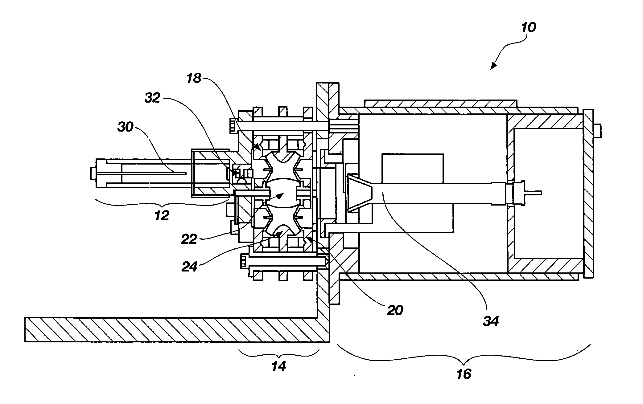
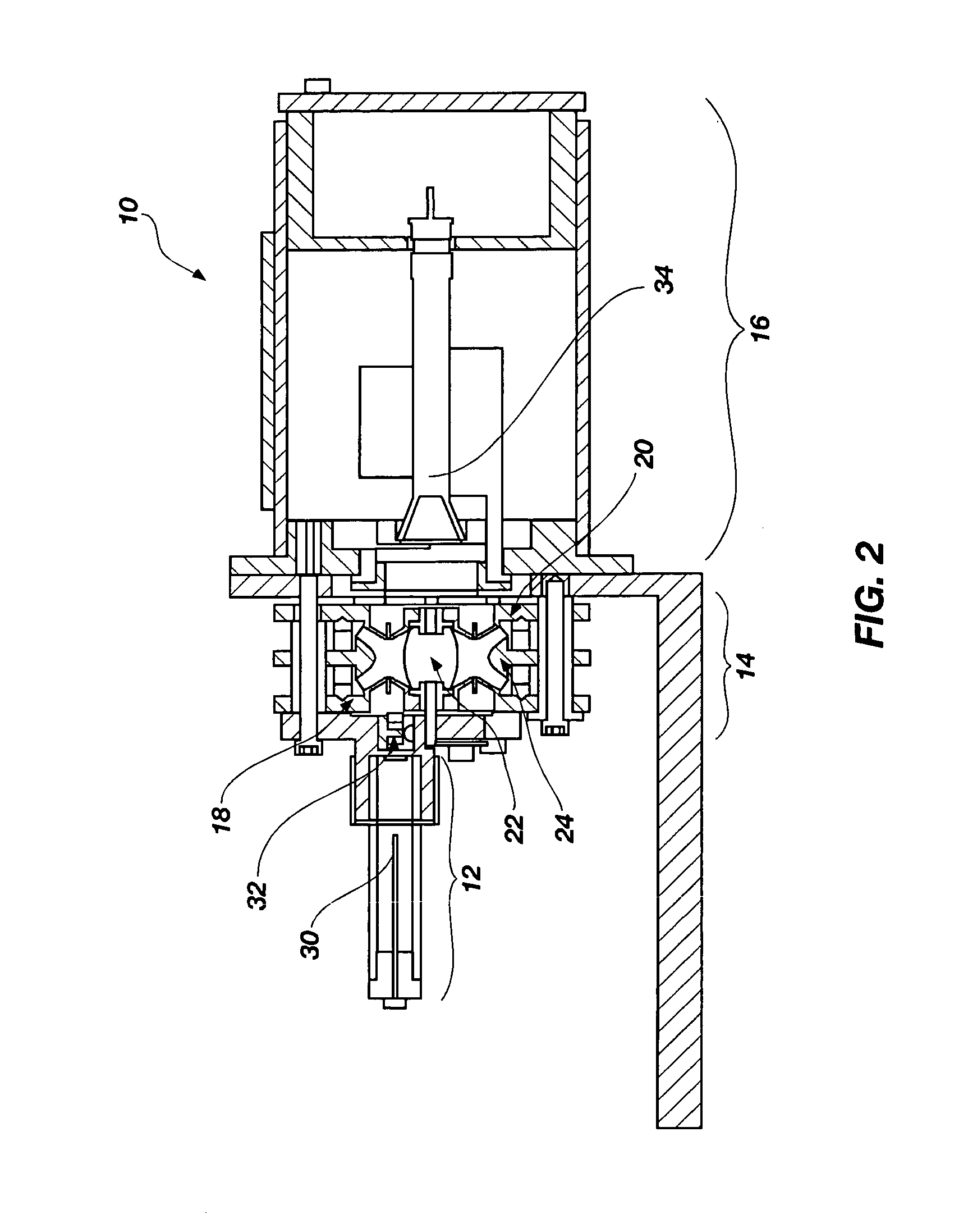
[0059]In the present invention, it is noted that a means must be provided wherein ions are admitted into and exit from the trapping region 14 as defined by the end caps 18, 20 and the inner ring 22 and the outer ring 24. Ion admission and ejection is accomplished by means of slits and recessed bridges in the filament endcap 18 and the detector endcap 20.

[0060]As the analyzer dimensions of ion trap mass analyzers become increasingly smaller, machining and other field imperfections can increase in their significance causing deleterious effects on the trapping and mass analysis capabilities of the ion trap. Discontinuities in the trapping field manifest themselves as perturbations to the desired essentially quadrupolar trapping field. A homogenous trapping field requires that the electrode surfaces be the same throughout the entire trapping volume. However, in order to provide for electron or ion admission into the trapping volume during ionization and mass ejection to the detector dur...

second embodiment

[0064]In a second embodiment, it is another aspect of the present invention to optimize the size of the miniature toroidal RF ion trap analyzer. Traditional, full-size commercial 3D ion trap mass analyzers have a trapping chamber radius on the order of 1 cm. As such, the maximum RF voltage applied to the ring electrode for a maximum mass range of 650 da, and an operating frequency (Ω) of 1.1 MHz is approximately 15 kVp-p. In contrast, a toroidal ion trap geometry with the same radial dimension and an approximate 3:1 ratio between the radius of the torus (R) to the radius of the cross-sectional trapping field (r0) would have roughly 400 times more ion storage volume than the conventional 3D analyzer. This higher ion capacity can be traded against analyzer size. In other words, a toroidal RF ion trap with approximately the same storage volume as an ion trap of conventional design can be much smaller. For the reasons described above, the resulting smaller ion trap operating parameter i...

third embodiment

[0067]In the present invention, it is another aspect of the invention that it is desirable to protect the detector from ions both inside and outside the trapping volume during ionization. There are several sources of these ions. For example, during the ionization event, a large ion current reaches a detector in the detector assembly 16 either indirectly (by scattering), through the ion trap analyzer, or due to the formation of ions whose stability parameters are outside the stability boundary and as such they are immediately ejected from the trap and into the detector. This excess, non-mass analyzed current has the deleterious effect of shortening the life of the detector. It is desirable to prevent detector signal during ionization to thereby increase the life of the detector.

[0068]One approach to address this problem is to turn the detector off during ionization and then back on for the subsequent mass analysis scan. Switching the detector voltages on and off, however, is slow at ...


PUM


Abstract

A scaled down version of a toroidal radio frequency (RF) ion trap mass analyzer operating with RF trapping voltages on the order of 1 kVp-p yet despite the reduced dimensions, retains roughly the same ion trapping volume as conventional 3D quadrupole ion traps, wherein the curved geometry enables construction of a compact mass analyzer and easy interface with conventional electron multipliers.

Description

CROSS REFERENCE TO RELATED APPLICATIONS [0001]This document claims priority to, and incorporates by reference all of the subject matter included in the U.S. Provisional Patent Application having docket number 05-62, with Ser. No. 60 / 750,277 and filed on Dec. 13, 2005.[0002]This invention was made with Government support under contract number DTRA 01-03-C-0047 PZ0001 with the Department of Defense, Defense Threat Reduction Agency, and under contract number DABJ 19-03-C-0005 with Dugway Proving Ground.BACKGROUND OF THE INVENTION[0003]1. Field of the Invention[0004]This invention relates generally to storage, separation and analysis of ions according to mass-to-charge ratios of charged particles and charged particles derived from atoms, molecules, particles, sub-atomic particles and ions. More specifically, the present invention is a relatively small and portable device for performing mass spectrometry using a miniature toroidal configuration for a mass analyzer.[0005]2. Description of...

Claims


Application Information

Patent Timeline
Patent Type & Authority Applications(United States)
IPC IPC(8): H01J49/36H01J49/04
CPCB01D59/44H01J49/0013H01J49/4225H01J49/422H01J49/423H01J49/424
Inventor LAMMERT, STEPHEN A.TOLLEY, SAMUEL E.JONES, JEFFREY L.WAITE, RANDALL W.LEE, EDGAR D.LEE, MILTON L.
Owner BRIGHAM YOUNG UNIV
Why Eureka
Try Eureka