Battery pack, method of determining malfunction, and a malfunction decision circuit

Active Publication Date: 2012-11-01
SANYO ELECTRIC CO LTD
View PDF4 Cites 24 Cited by
  • Summary
  • Abstract
  • Description
  • Claims
  • Application Information

AI Technical Summary

Benefits of technology

[0029]In the present invention, when the charging and discharging current is below the prescribed current and the count of number of times the rechargeable battery voltage rises from the second voltage to the first voltage is greater than or equal to a prescribed number, the current detection section is judged as malfunctioning. Consequently, when the conditions for determining current detection section malfunction are met over a prescribed number of repeated cycles, the reliability for practical judgment of current detection section malfunction is improved.
[0030]In the present invention, the prescribed number of counts of rechargeable battery voltage rise from the second voltage to the first voltage is set depending on the voltage difference between the first voltage and the second voltage, and the smaller (or larger) the voltage difference, the higher (lower) the prescribed number of counts. This improves reliability for judging whether or not the current detection section is malfunctioning even when rechargeable battery voltage variation during voltage rise is small.
[0031]In the present invention, when the time required for rechargeable battery voltage rise from the second voltage to the first voltage is greater than a prescribed time, evaluation of current detection section malfunction is not performed. This prevents mistaken determination of current detection section malfunction when the rechargeable batter

Problems solved by technology

If battery voltage exceeds the maximum battery voltage, battery lifetime and charging and discharging capacity degrade, and there is also risk of damage that even extends to battery combustion.
When a high current flows that exceeds the rechargeable battery maximum allowable current, the result can extend to rechargeable battery failure such as over-heating, combustion, and explosion.
Accordingly, if for some reason the current detection resistor, which is indispensible for remaining capacity computation and over-current detection, fails due to a condition such as short circuit, not only is the ability to accurately determine remaining battery capacity lost, but also rechargeable batt

Method used


Image

  • Battery pack, method of determining malfunction, and a malfunction decision circuit
  • Battery pack, method of determining malfunction, and a malfunction decision circuit
  • Battery pack, method of determining malfunction, and a malfunction decision circuit

Examples


Example

First Embodiment

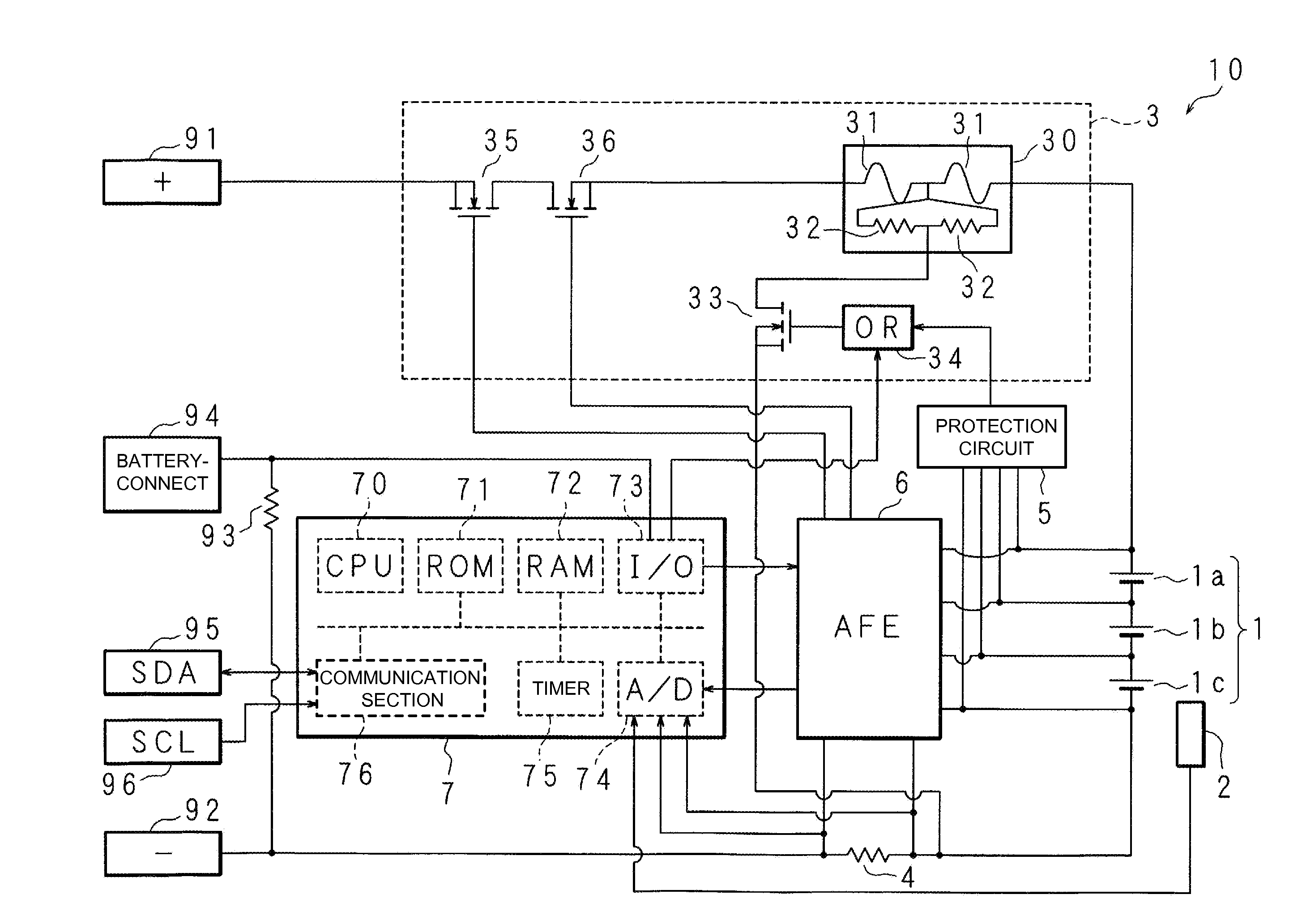
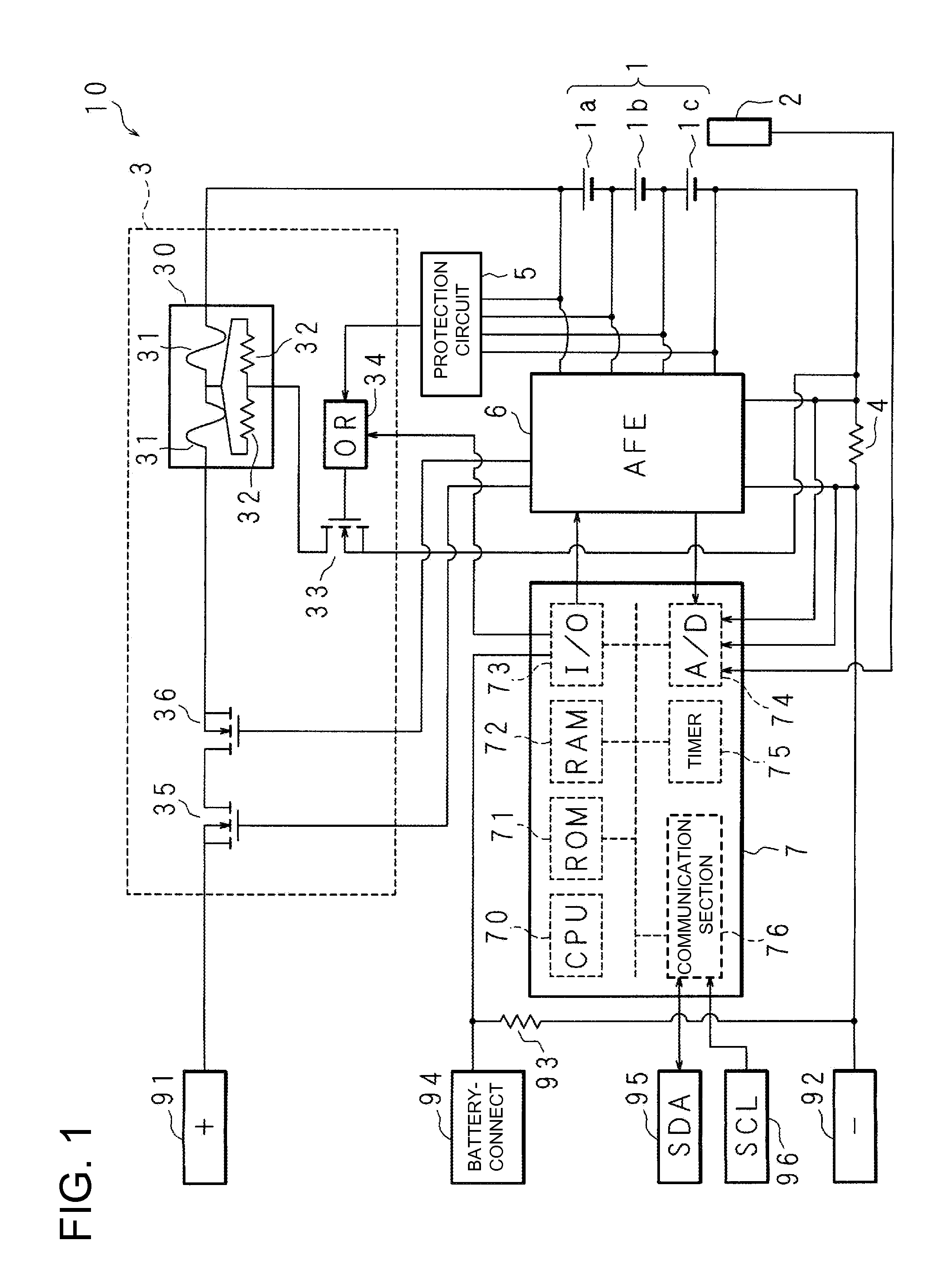
[0041]FIG. 1 is a block diagram showing an example of the circuit architecture for a battery pack of the present invention. The battery pack 10 of the figure is provided with a rechargeable battery 1 made up of battery cells 1a, 1b, 1c that are lithium ion batteries connected in series in that order, and a temperature sensor 2 that detects rechargeable battery temperature. The positive electrode terminal of battery cell la and the negative electrode terminal of battery cell 1c are equivalent to the positive and negative electrode terminals of the rechargeable battery 1. The rechargeable battery 1 can also be made up of other batteries such as nickel-hydride batteries or nickel cadmium batteries. Further, the number of rechargeable battery cells is not limited to three, and there could be one, two, or four or more battery cells as well.

[0042]The positive electrode terminal of the rechargeable battery 1 is connected to the positive (+) terminal 91 of the battery pack 1...

Example

Second Embodiment

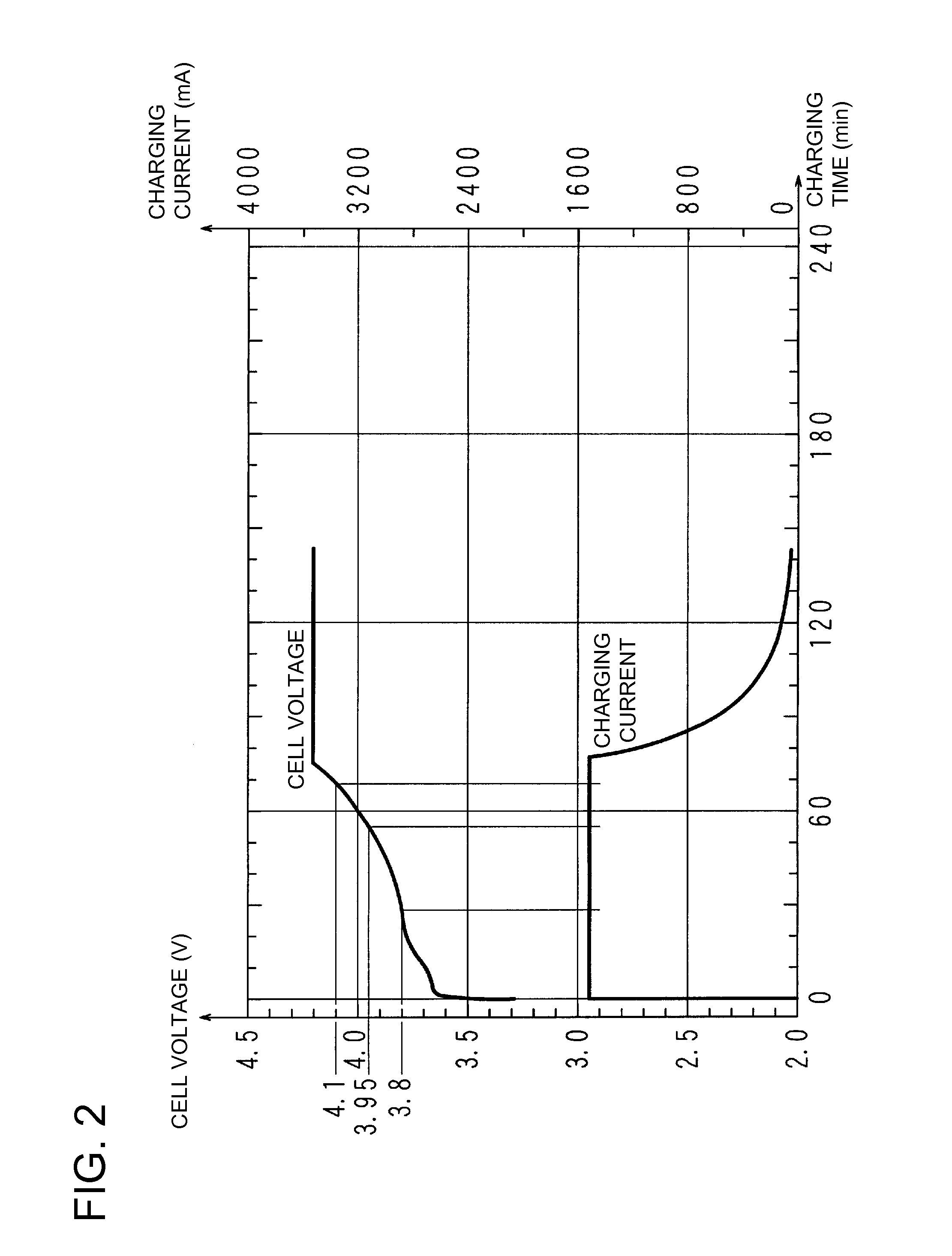
[0071]In the first embodiment, the second voltage is lower than the resume-charging voltage (3.95V). In addition, the first embodiment judges that the current detection section has malfunctioned when charging and discharging current is less than the prescribed current and the maximum cell voltage rises one time from a voltage below the second voltage to a voltage above the first voltage. In contrast, the second embodiment judges that the current detection section has malfunctioned when charging and discharging current is less than the prescribed current and the maximum cell voltage rises several times from a voltage below a second voltage, which is greater than or equal to the resume-charging voltage, to a voltage above the first voltage.

[0072]The battery pack 10 structure for the second embodiment and battery cell 1a, 1b, 1c voltage and charging current characteristics as a function of charging time are the same as in the first embodiment, and their detailed descri...


PUM


Abstract

Application of rechargeable battery 1 charging voltage is determined by a signal applied to a battery-connect terminal 94 from external electrical equipment. In the case of charging voltage application, the current detection section is judged as malfunctioning when the maximum battery cell 1a, 1b, 1c voltage detected as a time series rises from a voltage below 3.8V (the second voltage) to a voltage above 4.1V (the first voltage) even though rechargeable battery 1 charging and discharging current detected as a time series is (only) greater than −5 mA and less than 20 mA.

Description

BACKGROUND OF THE INVENTION[0001]1. Field of the Invention[0002]The present invention relates to a battery pack, to a method of determining malfunction that judges whether or not a current detection section, which detects rechargeable battery charging and discharging current, is operating abnormally, and to a malfunction decision circuit.[0003]2. Description of the Related Art[0004]State-of-the-art lithium ion battery charging (representative of rechargeable battery charging) charges batteries with a given current by constant current charging until the terminal voltage (referred to as battery voltage below) reaches a specified voltage set lower than the maximum allowable rechargeable battery voltage. Subsequently, charging switches to constant voltage charging. This is known as constant current-constant voltage charging and is the primary method in practice. If battery voltage exceeds the maximum battery voltage, battery lifetime and charging and discharging capacity degrade, and th...

Claims


Application Information

Patent Timeline
IPC IPC(8): G01R31/02
CPCG01R31/3624G01R35/00H01M10/4285H01M10/4257H01M10/425G01R31/3842Y02E60/10G01R19/16542
Inventor MATSUURA, SHINICHI
Owner SANYO ELECTRIC CO LTD
Why Eureka
Try Eureka