[0018]According to an embodiment of the present invention, a dimmable ballast circuit for a
compact fluorescent lamp generates a lamp current through the lamp having a substantially
constant envelope such that
flicker in the lamp
electromagnetic interference (EMI)
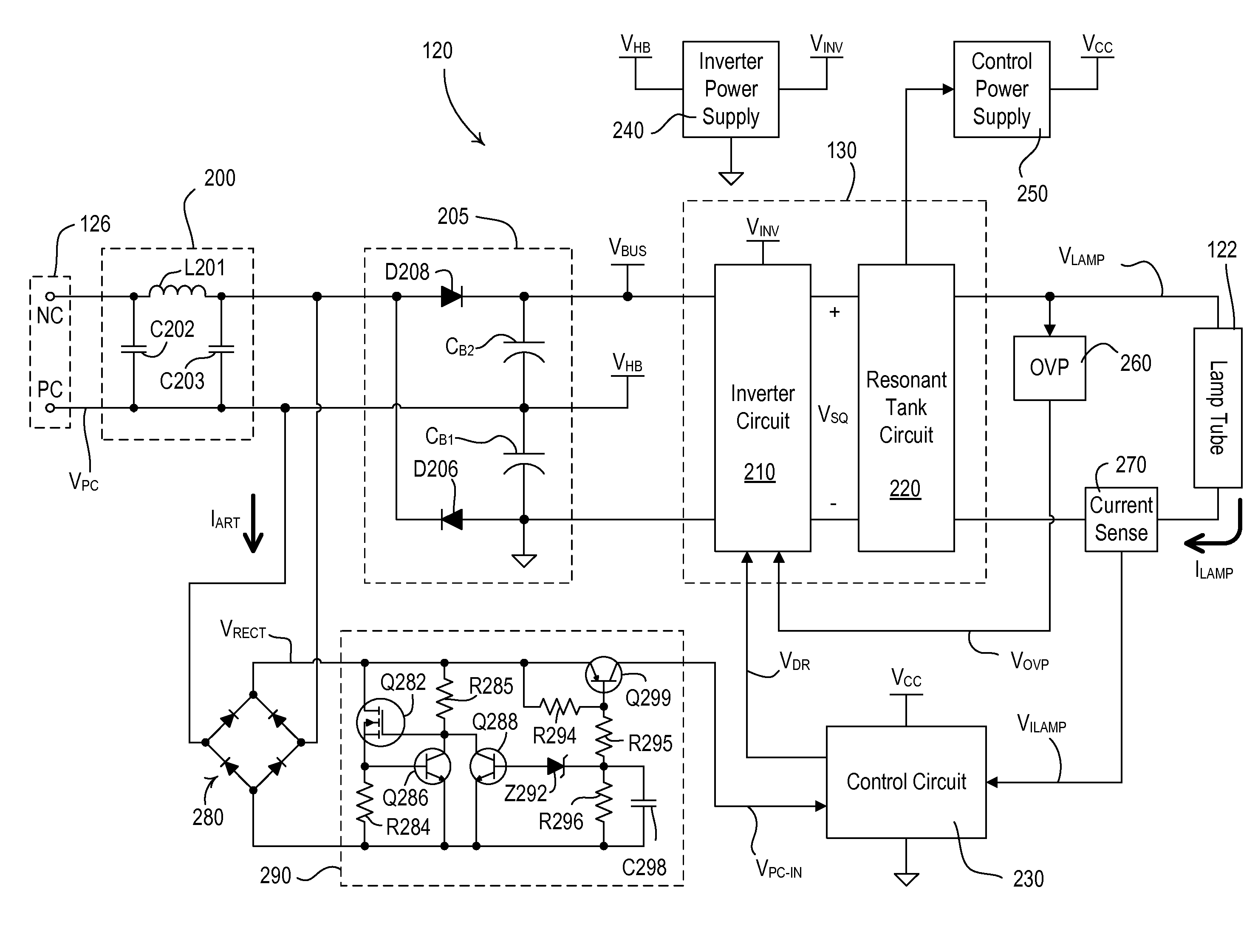
noise on an AC voltage supply is minimized. The ballast circuit comprises a
bus-voltage-generating circuit receiving an input from an AC voltage supply and producing a
DC bus voltage characterized by a low-frequency voltage
ripple, an
inverter circuit receiving the
DC bus voltage and generating a variable frequency square-wave output
signal, and an output filter circuit receiving the square-wave output
signal and generating a substantially sinusoidal lamp current through the lamp at the frequency. The
inverter circuit has a control input provided with a drive
control signal that determines the frequency of operation of the
inverter circuit and thus the frequency of the square-wave output signal. The ballast circuit further comprises a
control circuit producing the drive
control signal provided at the control input of the inverter circuit to control the frequency of the square-wave output signal and thus the intensity level of the lamp. The
control circuit receives a first signal related to a target intensity level of the lamp and a second signal related to the actual intensity level of the lamp. The
control circuit comprises an
error amplifier circuit for comparing the first and second signals to produce the drive
control signal to cause the inverter circuit to operate at a frequency to illuminate the lamp at the target intensity level. The
bus-voltage-generating circuit produces the
DC bus voltage to define an envelope for the sinusoidal lamp current, and the
error amplifier circuit operates in a frequency range such that the
error amplifier circuit is responsive to the second signal at the frequency of the second signal thereby to adjust the frequency of operation of the inverter circuit to reduce variation in the envelope of the sinusoidal lamp current.
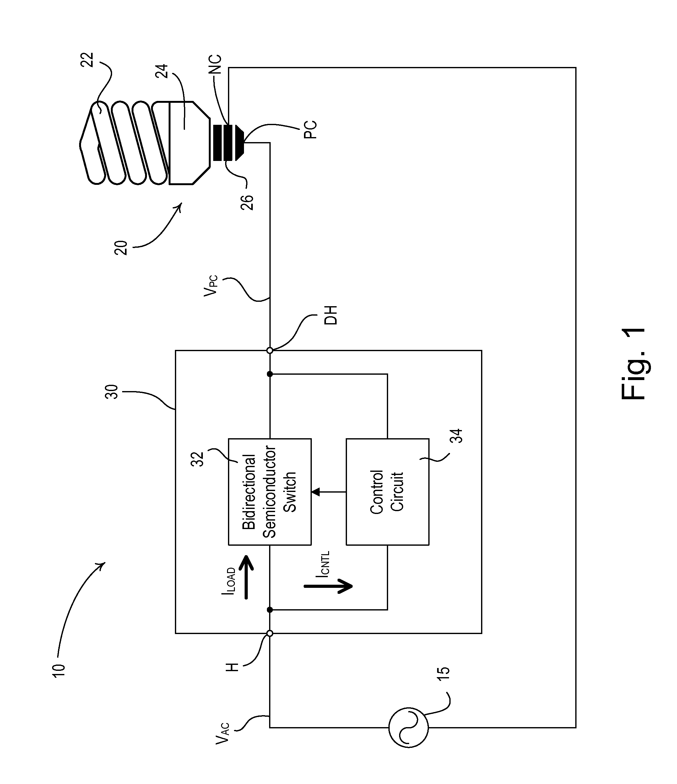
[0019]In addition, a dimmable compact
fluorescent lamp adapted to receive a phase-control voltage from a
dimmer switch is also described herein. The dimmable compact
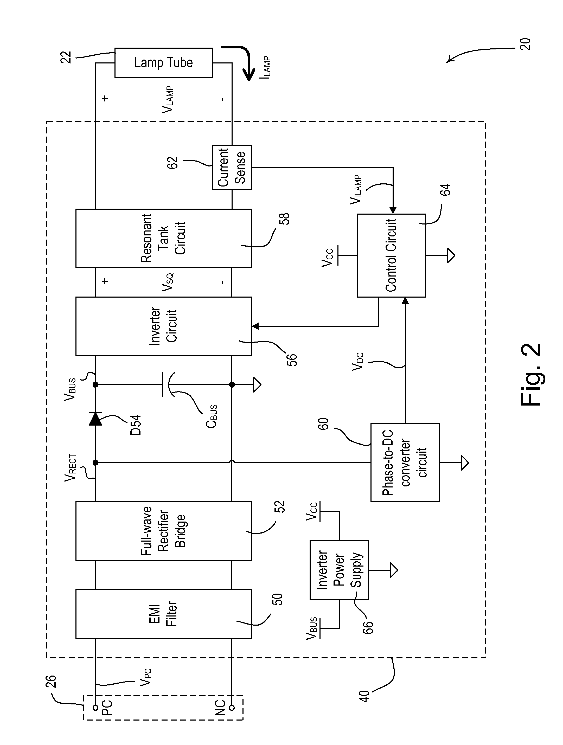
fluorescent lamp comprises a
fluorescent lamp tube, and an electronic ballast circuit for receiving the phase-control voltage from the
dimmer switch and illuminating the lamp tube in response to the phase-control voltage. The ballast circuit comprises an inverter circuit for generating a variable frequency square-wave output signal from a
DC bus voltage and an output filter circuit receiving the
square wave output signal and generating a substantially sinusoidal lamp current through the lamp tube at the frequency. The electronic ballast circuit further comprises a control circuit for producing a drive control signal that is provided to a control input of the inverter circuit to control the frequency of the square-wave output signal and thus the intensity level of the lamp tube. The control circuit receives a first signal related to a target intensity level of the lamp tube and a second signal related to the actual intensity level of the lamp tube. The control circuit comprises an error
amplifier circuit for comparing the first and second signals to produce the drive control signal to cause the inverter circuit to operate at a frequency to illuminate the lamp tube at the target intensity level. The
DC bus voltage defines an envelope for the sinusoidal lamp current, and the error
amplifier circuit operates in a frequency range such that the error
amplifier circuit is responsive to the second signal at the frequency of the second signal thereby to adjust the frequency of operation of the inverter circuit to reduce variation in the envelope of the sinusoidal lamp current.
[0020]According to another embodiment of the present invention, a
lighting control system receiving power from an
AC power source comprises a dimmable compact fluorescent lamp and a dimmer switch adapted to be coupled in series
electrical connection between the
AC power source and the dimmable compact fluorescent lamp. The dimmable compact fluorescent lamp includes a fluorescent lamp tube and an electronic ballast circuit for illuminating the lamp tube. The dimmer switch generates a phase-control voltage characterized by a
duty cycle defining a target intensity level of the lamp tube of the dimmable compact fluorescent lamp. The electronic ballast circuit receives the phase-control voltage and illuminates the lamp tube in response to the phase-control voltage. The ballast circuit comprises an inverter circuit for generating a variable frequency square-wave output signal from a
DC bus voltage and an output filter circuit receiving the square-wave output signal and providing a substantially sinusoidal lamp current through the lamp tube at the frequency. The electronic ballast circuit further comprises a control circuit for producing a drive control signal that is provided to a control input of the inverter circuit to control the frequency of the square-wave output signal and thus the intensity level of the lamp tube. The DC
bus voltage defines an envelope for the sinusoidal lamp current, and the control circuit operates in a frequency range such that the control circuit adjusts the frequency of operation of the inverter circuit to reduce variation in the envelope of the sinusoidal lamp current.
[0021]According to another aspect of the present invention, a dimmable ballast circuit for a fluorescent lamp comprises: (1) an inverter circuit generating a variable frequency square-wave output signal, the inverter circuit having a control input provided with a drive control signal that determines the frequency of operation of the inverter circuit and thus the frequency of the square -wave output signal; (2) an output filter circuit receiving the
square wave output signal and generating a substantially sinusoidal lamp current through the lamp at the frequency; (3) a non-
linear amplifier circuit amplifying a lamp-current-feedback signal representative of the magnitude of the lamp current through the lamp; and (4) a control circuit producing the drive control signal provided at the control input of the inverter circuit to control the frequency of the square-wave output signal and thus the intensity level of the lamp. The control circuit receives a target-intensity signal related to a target intensity level of the lamp and compares the target-intensity signal and the lamp-current-feedback signal to produce the drive control signal. The control circuit operates at a bandwidth greater than approximately 10 kHz to cause the inverter circuit to operate at a frequency in order to illuminate the lamp at the target intensity level. For first values of the lamp current that are below a
current threshold, the lamp-current-feedback signal is amplified by a first amount, and for second values of the lamp current that are above the
current threshold, the lamp-current-feedback signal is amplified by a second, smaller amount, thereby increasing responsiveness of the control circuit to changes in lamp intensity levels at low lamp intensity levels.

