Tunable filter

a filter and filtering technology, applied in the field of tunable filters, can solve the problem of small absolute value of frequency-temperature coefficient tcf, and achieve the effect of increasing the variable amount of the frequency of the pass band

Active Publication Date: 2012-11-15
MURATA MFG CO LTD
View PDF16 Cites 124 Cited by
  • Summary
  • Abstract
  • Description
  • Claims
  • Application Information

AI Technical Summary

Benefits of technology

[0018]In another specific aspect of the tunable filter according to a preferred embodiment of the present invention, a concave portion is formed on a top surface of the piezoelectric substrate, an electrode located on the piezoelectric substrate is an IDT electrode, the elastic wave resonator is a surface acoustic wave resonator, and the IDT electrode includes metal with which the concave portion is filled. In this case, it is possible to increase the electromechanical coupling coefficient of the surface acoustic wave resonator. Accordingly, it is possible to widen a band width and it is also possible to widen the variable frequency range of the tunable filter.
[0019]In another specific aspect of the tunable filter according to a preferred embodiment of the present invention, the surface acoustic wave resonator further includes an Si02 film arranged so as to cover a top surface of the piezoelectric substrate. In this case, it is possible to decrease the absolute value of the frequency-temperature coefficient TCF of the surface acoustic wave resonator. Accordingly, it is possible to improve the temperature characteristic of the tunable filter.
[0023]In another specific aspect of the tunable filter according to a preferred embodiment of the present invention, the tunable filter further includes a package, wherein the bandwidth extending inductance is a conductor pattern of a spiral shape or a meander shape, and the conductor pattern of a spiral shape or a meander shape is disposed on the piezoelectric substrate or in the package. In this case, since it is possible to provide the bandwidth extending inductance using the conductor pattern located on the piezoelectric substrate or in the package, it is possible to achieve the miniaturization of the tunable filter.
[0031]In another specific aspect of the tunable filter according to a preferred embodiment of the present invention, each of a fractional band width of the series arm resonator and a fractional band width of the parallel arm resonator is greater than or equal to about 13% and less than or equal to about 60%, for example. In this case, it is possible to further increase the frequency variable amount. More preferably, the fractional band width of each of the series arm resonator and the parallel arm resonator is greater than or equal to about 15%, for example. In that case, it is possible to further increase the frequency variable amount.

Problems solved by technology

However, in the tunable filter 1101 described in Japanese Unexamined Patent Application Publication No. 2005-217852, there has occurred a problem that the surface acoustic wave resonators used for the series arm resonators 1104 and 1105 and the parallel arm resonators 1106 and 1107 have small electromechanical coupling coefficients and the absolute value of a frequency-temperature coefficient TCF is small.

Method used


Image

  • Tunable filter
  • Tunable filter
  • Tunable filter

Examples


first preferred embodiment

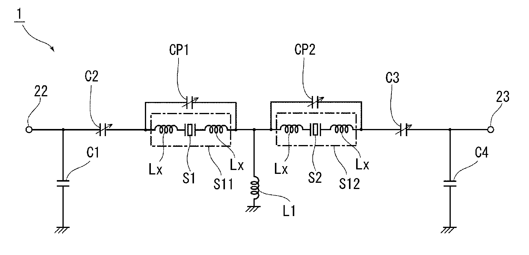
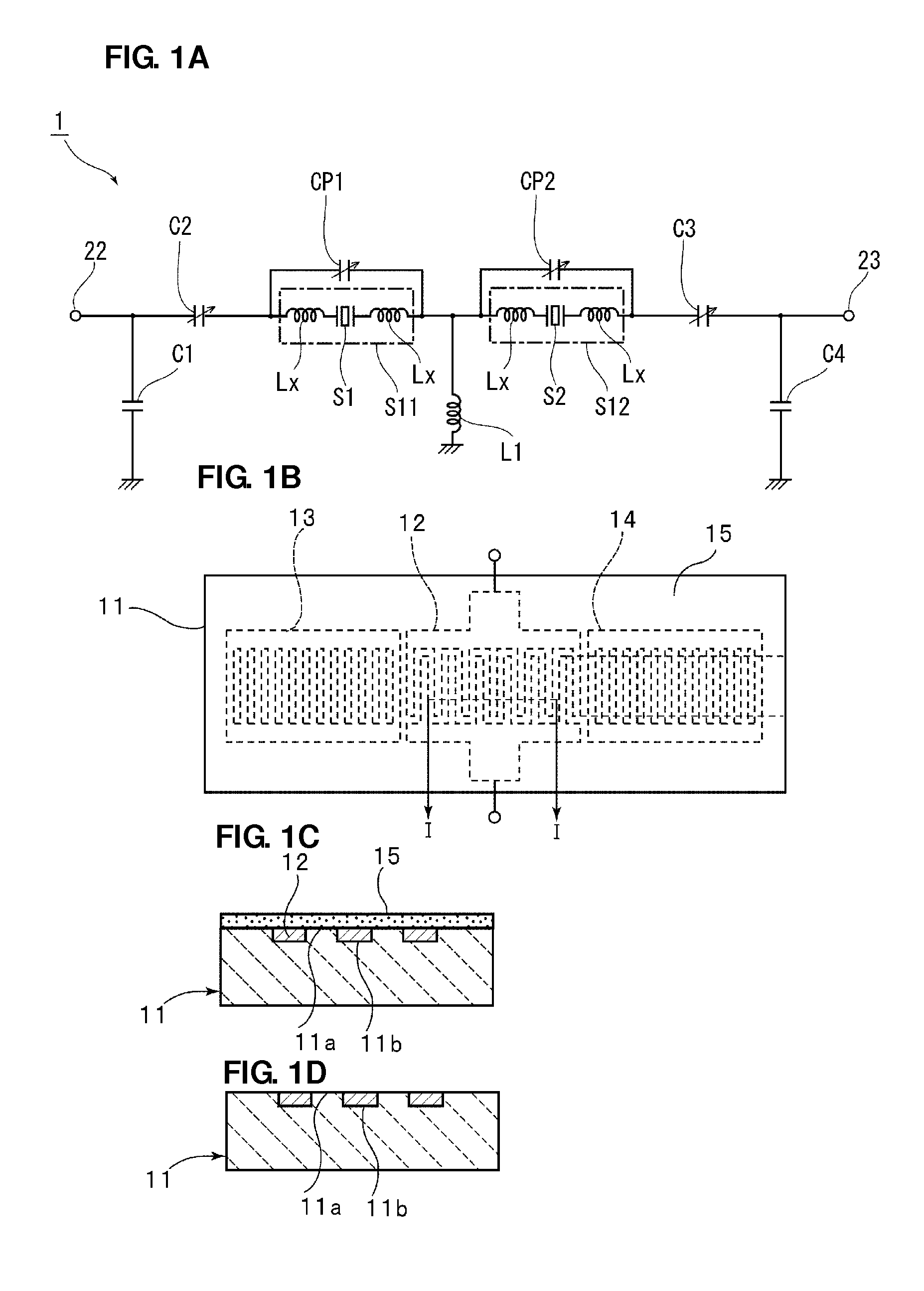
[0090]FIG. 1A is a circuit diagram of a tunable filter according to a first preferred embodiment of the present invention, FIG. 1B is a schematic plan view of a surface acoustic wave resonator used in the tunable filter, and FIG. 1C is the elevational cross-sectional view of a portion taken along a I-I line in FIG. 1B. FIG. 1D is the elevational cross-sectional view of a structure in which no Si02 film in FIG. 1C exists.

[0091]In a tunable filter 1 in FIG. 1A, in a series arm connecting an input terminal 22 and an output terminal 23 to each other, series arm resonator circuit portions S11 and S12 are connected in series to each other. In the series arm resonator circuit portion S11, on both sides of a series arm resonator S1, inductances Lx and Lx are connected in series to the series arm resonator S1. In the same way, in the series arm resonator circuit portion S12, on both sides of a series arm resonator S2, inductances Lx and Lx are connected in series to the series arm resonator ...

first experimental example

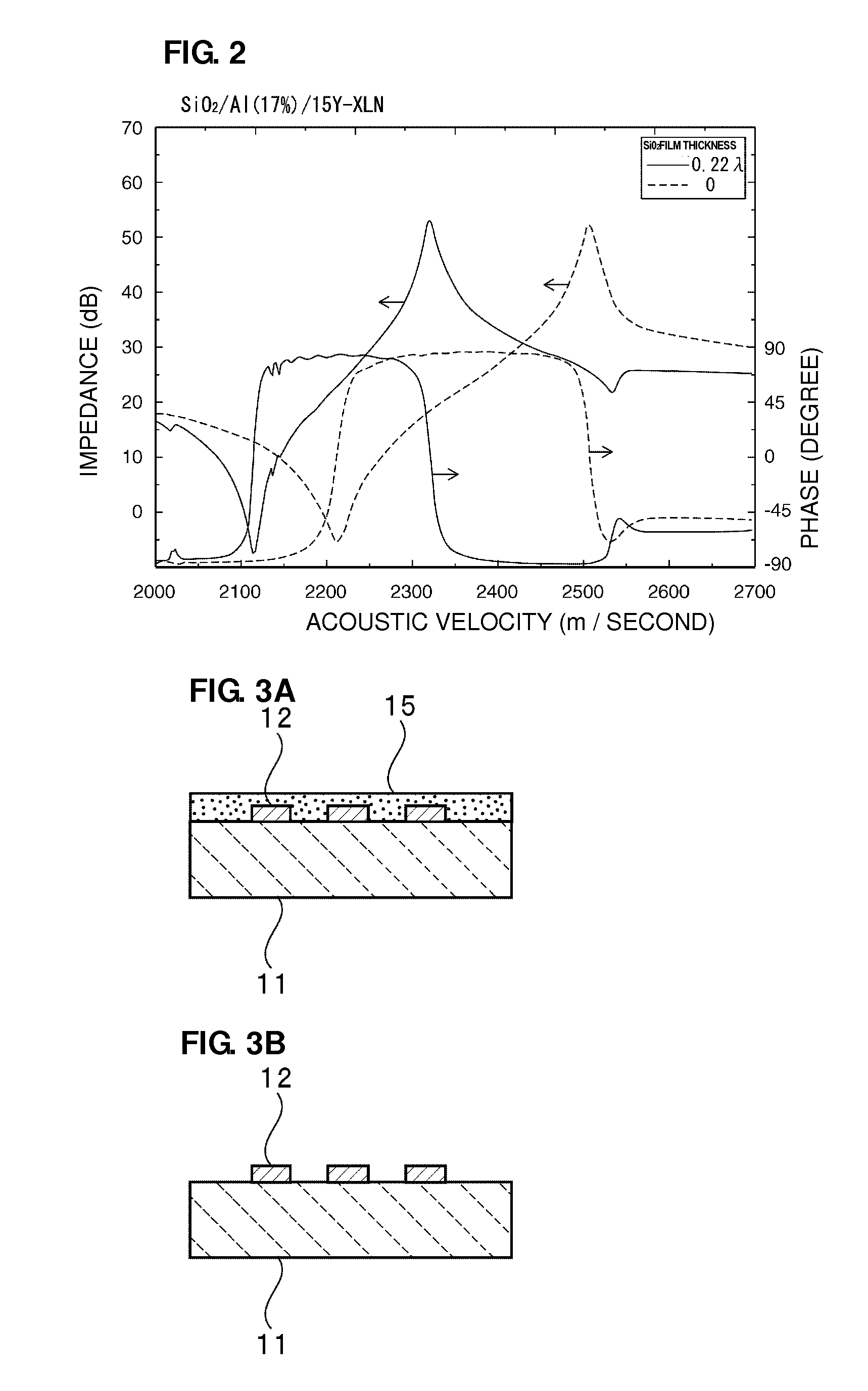
[0106]Solid lines in FIG. 2 are diagrams illustrating the impedance characteristic and the phase characteristic of a surface acoustic wave resonator when the film thickness of the IDT electrode 12 is about 0.17λ and the film thickness of an Si02 film is about 0.22λ on condition that a LiNbO3 substrate of 15° Y-cut X-propagation, such as a LiNbO3 substrate with Euler angles of (0°, 105°, 0°), is used, Al is used as electrode material, and the wave length of the surface acoustic wave resonator is λ. For comparison, dashed lines in FIG. 2 illustrate the impedance-frequency characteristic and the phase characteristic of the surface acoustic wave resonator illustrated in FIG. 1D formed in the same way except that no Si02 film is provided.

[0107]As is clear from FIG. 2, a top / bottom ratio, the ratio of an impedance at an anti-resonant point to an impedance at a resonant frequency, was about 57.5 dB when no Si02 film was provided. On the other hand, it was possible to increase the top / botto...

second experimental example

[0109]A LiTaO3 substrate with Euler angles of (0°, 126°, 0°) was used as a piezoelectric substrate, Au was used as electrode material, an Si02 film was subjected to film formation so as to cover the piezoelectric substrate, and surface acoustic wave resonators with various structures were manufactured. When it was assumed that a wave length defined by the electrode finger pitch of an IDT electrode in a surface acoustic wave resonator was λ, it was assumed that a normalized thickness h / λ, obtained by normalizing the thickness h of an Si02 film by the wave length λ, was about 0.3. As prepared surface acoustic wave resonators, the following first to fifth surface acoustic wave resonators A to E were prepared.

[0110]The first surface acoustic wave resonator A: A structure in which, as illustrated in FIG. 3A, the IDT electrode 12 is provided on the top surface of the piezoelectric substrate 11 and the Si02 film 15 is further provided. In the top surface of the Si02 film, a convex portion ...


PUM


Abstract

A tunable filter that is capable of magnifying a pass band width or increasing a frequency variable amount includes a resonator circuit portion provided in at least one of a series arm connecting an input terminal and an output terminal to each other and a parallel arm connecting the series arm and a ground potential to each other, a first variable capacitor is connected in series to the resonator circuit portion and a second variable capacitor is connected in parallel to the resonator circuit portion. The resonator circuit portion includes a piezoelectric substrate including LiNbO3 or LiTaO3, an elastic wave resonator including an electrode located on the piezoelectric substrate, and a bandwidth extending inductance Lx, Lx connected to the elastic wave resonator.

Description

BACKGROUND OF THE INVENTION[0001]1. Field of the Invention[0002]The present invention relates to a tunable filter preferably for use as a passband filter in a communication system, and in more detail, relates to a tunable filter including an elastic wave resonator.[0003]2. Description of the Related Art[0004]Occasionally, in a passband filter used in a communication system, a pass band is desired to be adjustable. Various passband filters, such as tunable filters, which satisfy this requirement, have been proposed.[0005]For example, Japanese Unexamined Patent Application Publication No. 2005-217852 discloses a tunable filter that uses a plurality of surface acoustic wave resonators and a plurality of variable capacitors. FIG. 46 is a circuit diagram of the tunable filter described in Japanese Unexamined Patent Application Publication No. 2005-217852.[0006]In a tunable filter 1101, a plurality of series arm resonators 1104 and 1105 are connected in series to a series arm that connect...

Claims


Application Information

Patent Timeline
Patent Type & Authority Applications(United States)
IPC IPC(8): H03H9/54H03H9/64
CPCH03H7/12H03H7/38H03H9/02559H03H9/0542H03H9/6403H03H2009/02204H03H7/175H03H7/1708H03H9/542H03H9/6483H03H2007/386H03H9/64H03H9/25H10N30/85
Inventor KADOTA, MICHIOKOBAYASHI, HIDEAKIOGAMI, TAKASHI
Owner MURATA MFG CO LTD
Why Eureka
Try Eureka