Illumination Methods And Systems For Improving Image Resolution Of Imaging Systems

a technology of image resolution and imaging system, applied in the field of image resolution improvement, can solve the problems of inability to observe structures, inability to study transparent or thin specimens, and inability to study in-vivo targets such as microvascular structures, and achieve the effects of reducing or avoiding direct illumination of unrelated regions, reducing redirected light, and improving image resolution

Inactive Publication Date: 2012-11-15
ZHANG MIAO +1
View PDF4 Cites 15 Cited by
  • Summary
  • Abstract
  • Description
  • Claims
  • Application Information

AI Technical Summary

Benefits of technology

[0007]In one aspect of the invention, a reflection illumination method for an imaging system is provided. The reflection illumination method comprises illuminating an object including at least one target region with at least one illumination beam; detecting light redirected by the object from a detectable region of the imaging system; wherein the at least one illumination beam is focused such that the size of a projected illumination beam spot at the target region is reduced. As a result, the noises detected by the imaging system can be reduced, and therefore improving image sharpness and the signal-to-noise ratio.
[0012]In another aspect of the invention, the method of reducing direct illumination of the unrelated regions in the detectable region of the imaging system and pin-point focusing illumination beams are combined to achieve the benefits of both.
[0017]In yet another aspect of the invention, a method is provide to reduce the redirected light, including reflected as well as scattered and other, from being generated by the unrelated regions in the detectable region of the imaging system. Furthermore, a system is provided to distinguish the region of the field of view from the region of the projected beam spot. Thus, the projected beam spot is operated primarily off the center of the field of view and can be adjusted by users.
[0018]Therefore, image resolution can be improved by reducing or avoiding direct illumination of unrelated regions, particularly in the detectable region of the imaging system.

Problems solved by technology

The trans-illumination method, though used to study a transparent or thin specimen, is not suitable for observing structures underneath opaque thick tissues because light cannot pass through them.
Microscopic study of in-vivo targets, such as micro vascular structures, underneath tissues poses a severe low-signal, high-noise challenge.
Moreover, these useful signals are more and more likely to be further absorbed or redirected, without being detected by the imaging system.
Thus, as the observation layer goes deeper underneath the tissue surface, the intensity of the useful signals detected by imaging system becomes extremely small so that they are buried by the unrelated signals, also called noises, generated outside the target region, and the resulted images are too blurry and noisy to be useful.
Existing methods offer some marginal improvements, but the challenge remains.
As a result, today's intravital microscope, though capable of providing a micron or sub-micron resolution when studying thin slice specimens, can only achieve a much lower resolution when studying thick tissues.
For example, in human microcirculatory studies, the image quality offered by the current intravital microscope is incapable of providing information regarding the structure of capillary wall in an in-vivo study.
This limits further progress in microcirculatory studies and its potential applications in clinical research and practice.

Method used


Image

  • Illumination Methods And Systems For Improving Image Resolution Of Imaging Systems
  • Illumination Methods And Systems For Improving Image Resolution Of Imaging Systems
  • Illumination Methods And Systems For Improving Image Resolution Of Imaging Systems

Examples


Embodiment Construction

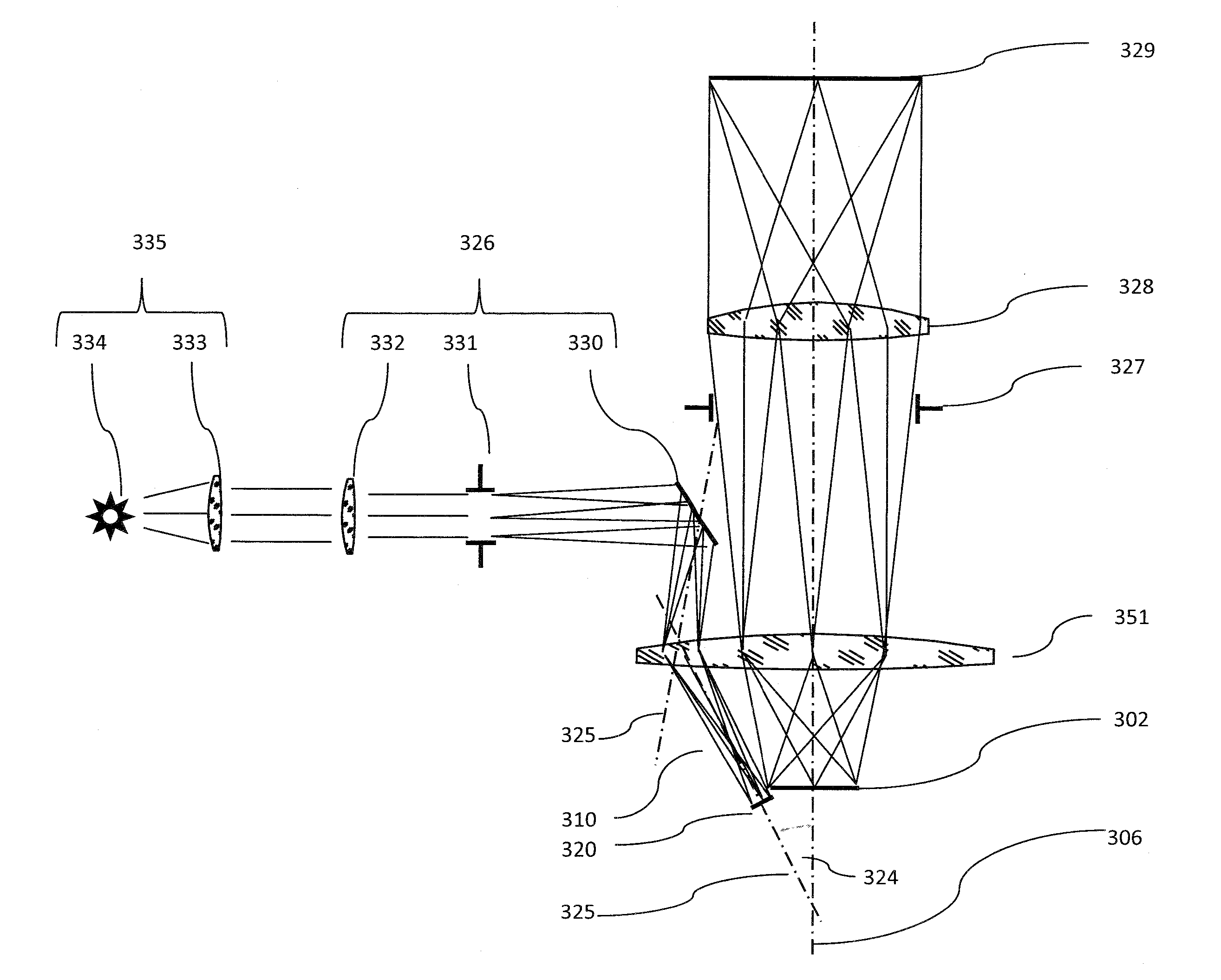
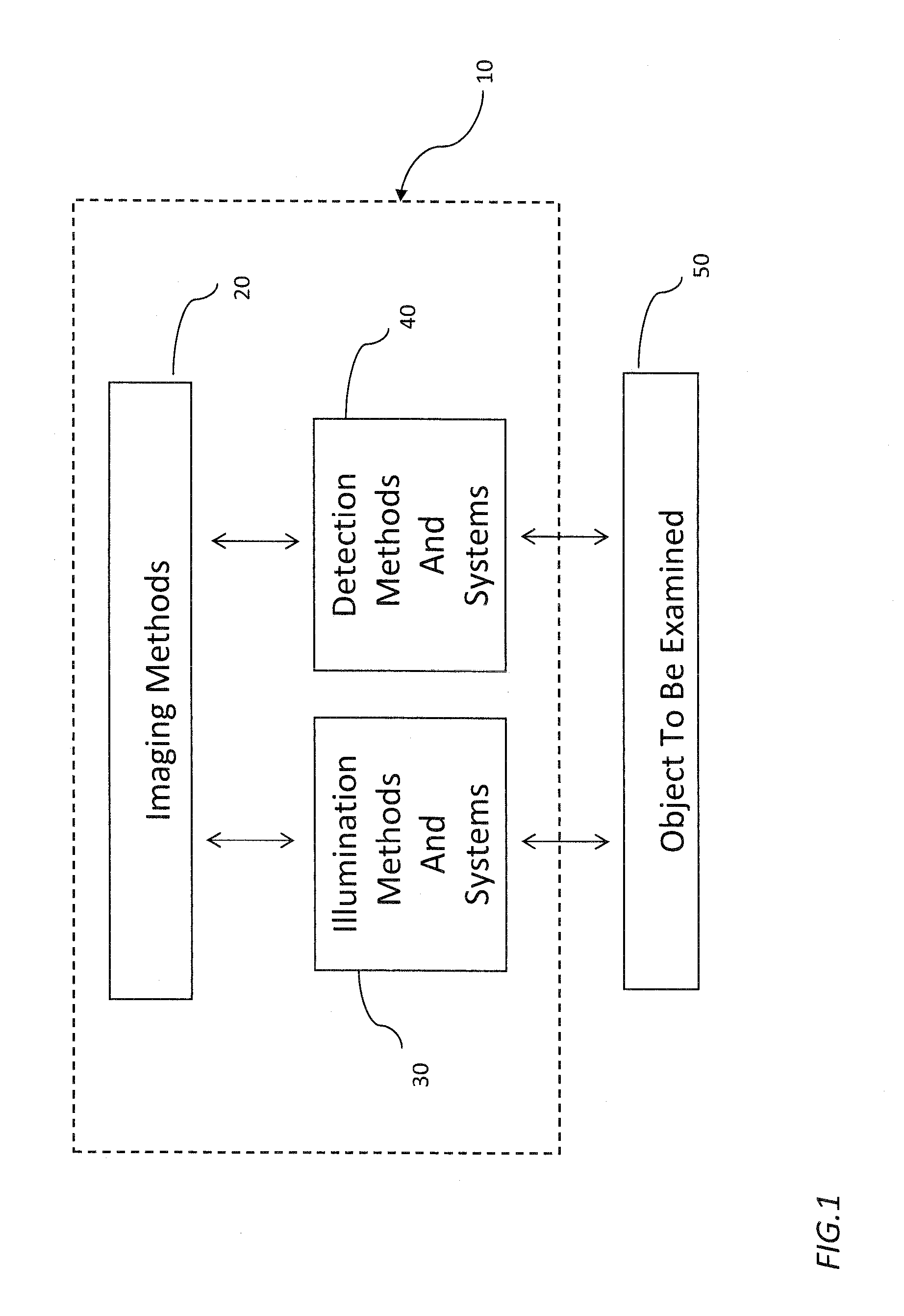
[0028]FIG. 1 shows a block diagram of an embodiment of the imaging system according to the principles of the invention. The imaging system such as a microscopic system 10 use imaging methods 20 including illumination methods and detection methods. It has an illumination system 30 to illuminate light or electromagnetic wave in general onto an object or a target 50 to be studied. The object 50, for example, can be a tissue under investigation. The object 50 include the target region of study 309. The region inside the object but outside the target region 309 is called unrelated regions of study. It also has a detection system 40 to detect redirected light from the object 50. In the case of microscope, the microscopic imaging methods 20 that can be used on this system include, but are not limited to, the optical microscope, the Fluorescence Microscope, the OPS Microscope and the Confocal Microscope.

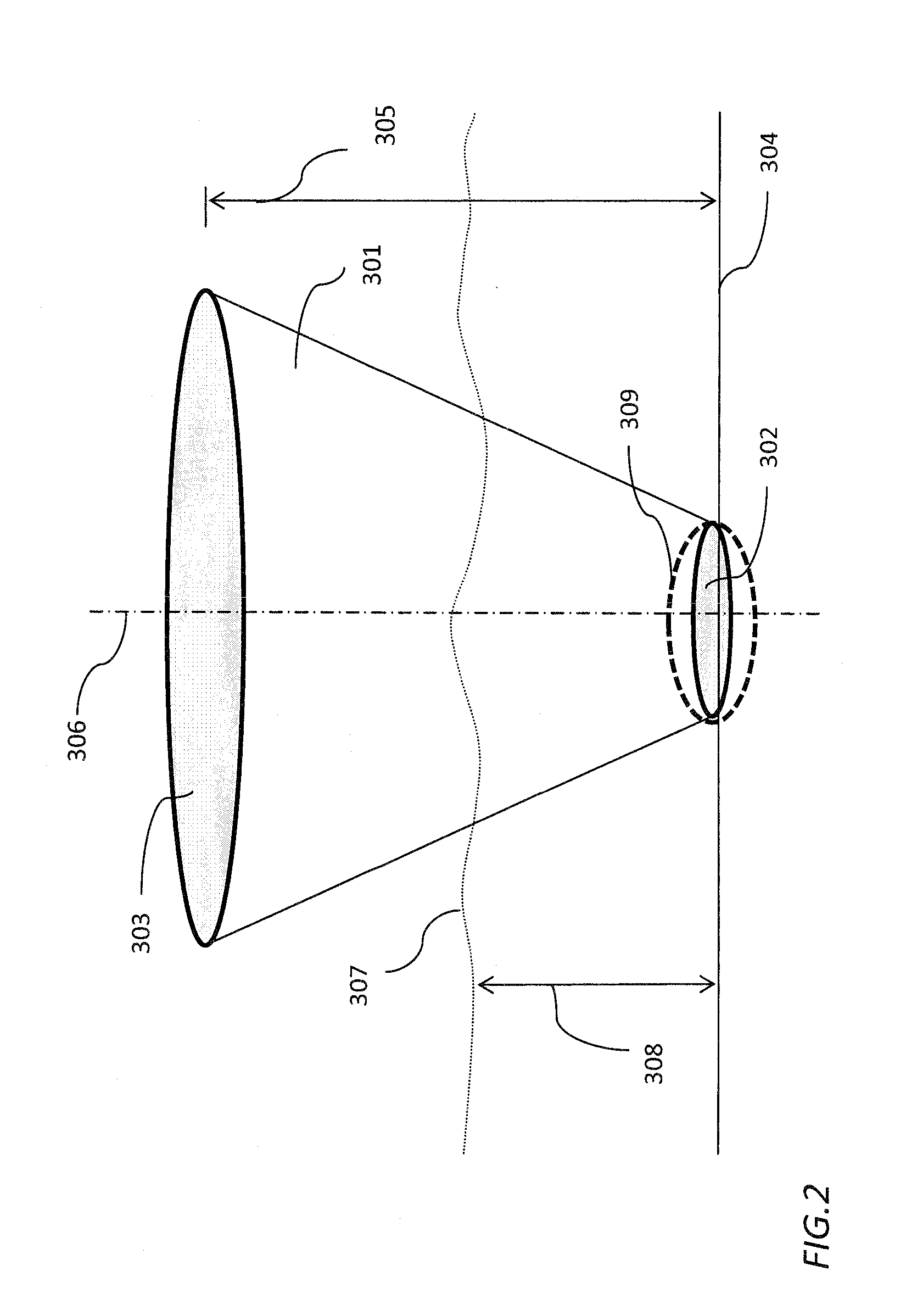
[0029]FIG. 2 shows the new concept of the detectable region of the imaging system, using...


PUM


Abstract

Method and systems for improving resolution of imaging systems, such as a microscope or a medical ultrasonic scanner, are provided. The resolution of the microscope is improved by reducing direct illumination of unrelated regions of an object under examination. According to an aspect of the present invention, a method is provided to reduce the direct illumination of the unrelated regions in a detectable region such as a cone of light that otherwise could generate substantial noises. In another aspect of the invention, a method is provided that focuses the illumination beams such that the width of the projected beam spot is narrowed, preventing the generation of a large amount of noise. In particular, the width of the illumination beam is narrowed such that the size of the projected illumination beam is smaller than the field of view of the microscope. In another aspect of the invention, a system according to the principles of the present invention is provided, wherein the illumination beam of light is such arranged that the overlap of the path of the illumination beam of light and the detectable region is reduced.

Description

FIELD OF THE INVENTION[0001]This invention relates to illumination methods and systems for improving image resolution and reducing image noises in imaging systems, and, more particularly, to illumination methods and systems for improving resolution and reducing noises of microscopes in in-vivo, high-resolution or real-time applications.BACKGROUND OF THE INVENTION[0002]In an imaging system such as a microscope or a medical ultrasonic scanner, when electromagnetic wave, such as visible light or ultrasonic wave is directed on an object, the electromagnetic wave, also referred to light, will be interacted with the object. Specifically, when an object such as a tissue is illuminated by light, a chain of interactions between light and the tissue occurs. These interactions include reflection, refraction, scattering, diffusion, diffraction, etc., all of which change the light path (i.e., redirection) and other light properties (e.g., intensity, phase, and polarization). The interactions als...

Claims


Application Information

Patent Timeline
Patent Type & Authority Applications(United States)
IPC IPC(8): A61B1/06A61B8/13A61B6/00
CPCA61B8/54A61B19/5223G02B21/06A61B19/5202G02B21/0012A61B90/30A61B90/20
Inventor ZHANG, MIAOHU, HUI
Owner ZHANG MIAO
Why Eureka
Try Eureka