Near-field light emitter, light-assisted magnetic recording head and light-assisted magnetic recording device

Inactive Publication Date: 2012-11-22
KONICA MINOLTA INC
View PDF0 Cites 4 Cited by
  • Summary
  • Abstract
  • Description
  • Claims
  • Application Information

AI Technical Summary

Benefits of technology

[0023]According to the inventions recited in Claim 1 through Claim 9, the electric field component of the light, which is to be coupled to the optical waveguide, oscillates within the oscillation surface being substantially perpendicular to the partial surface. Further, the metal structural body is arranged along the partial surface among the outer circumferential surface of the core. Accordingly, the oscillation surface of the electric field component becomes substantially perpendicular to the metal structural body that is shaped in substantially a plain plate. Therefore, it becomes possible to effectively excite the surface plasmon at the boundary between the core and the metal structural body.
[0024]Further, according to the inventions recited in Claim 1 through Claim 9, by forming the appropriate low refractive layer at the position between the clad and the metal structural body, it becomes possible to make the propagation constant of the optical waveguide and the number of waves of the surface plasmon substantially coincide with each other, and to reduce the loss constant of the surface plasmon. For this reason, it becomes possible to efficiently generate the near field light towards the light emitting section of the optical waveguide.
[0025]Specifically, in the invention recited in Claim 2, the refractive indexes of core and clad are established in such a manner that the refractive index of core becomes higher than that of the clad, and the ratio refractive-index difference Δ becomes equal to or greater than 0.25. In other words, the optical waveguide forms a high refractive-index difference waveguide. This makes it possible to concentrate the electric field along the core-clad boundary. On this reason, by employing the structural configuration of the near field light generator recited in Claim 2, it becomes possible to make the electric field component and the magnetic field component, both coupled to the optical waveguide, effectively condense.
[0026]Specifically, according to th

Problems solved by technology

According to the technologies set forth in Patent Documents 1 and 2, the structure for obliquely guiding the light to the scatterer is complicated.
As a result, the technologies set forth in Patent Documents 1 and 2 has arisen various kinds of problems to b

Method used


Image

  • Near-field light emitter, light-assisted magnetic recording head and light-assisted magnetic recording device
  • Near-field light emitter, light-assisted magnetic recording head and light-assisted magnetic recording device
  • Near-field light emitter, light-assisted magnetic recording head and light-assisted magnetic recording device

Examples


Example

[0079]Referring to the drawings, embodiments of the present invention will be detailed in the following.

1. Configuration of Light Assisted Magnetic Recording Apparatus

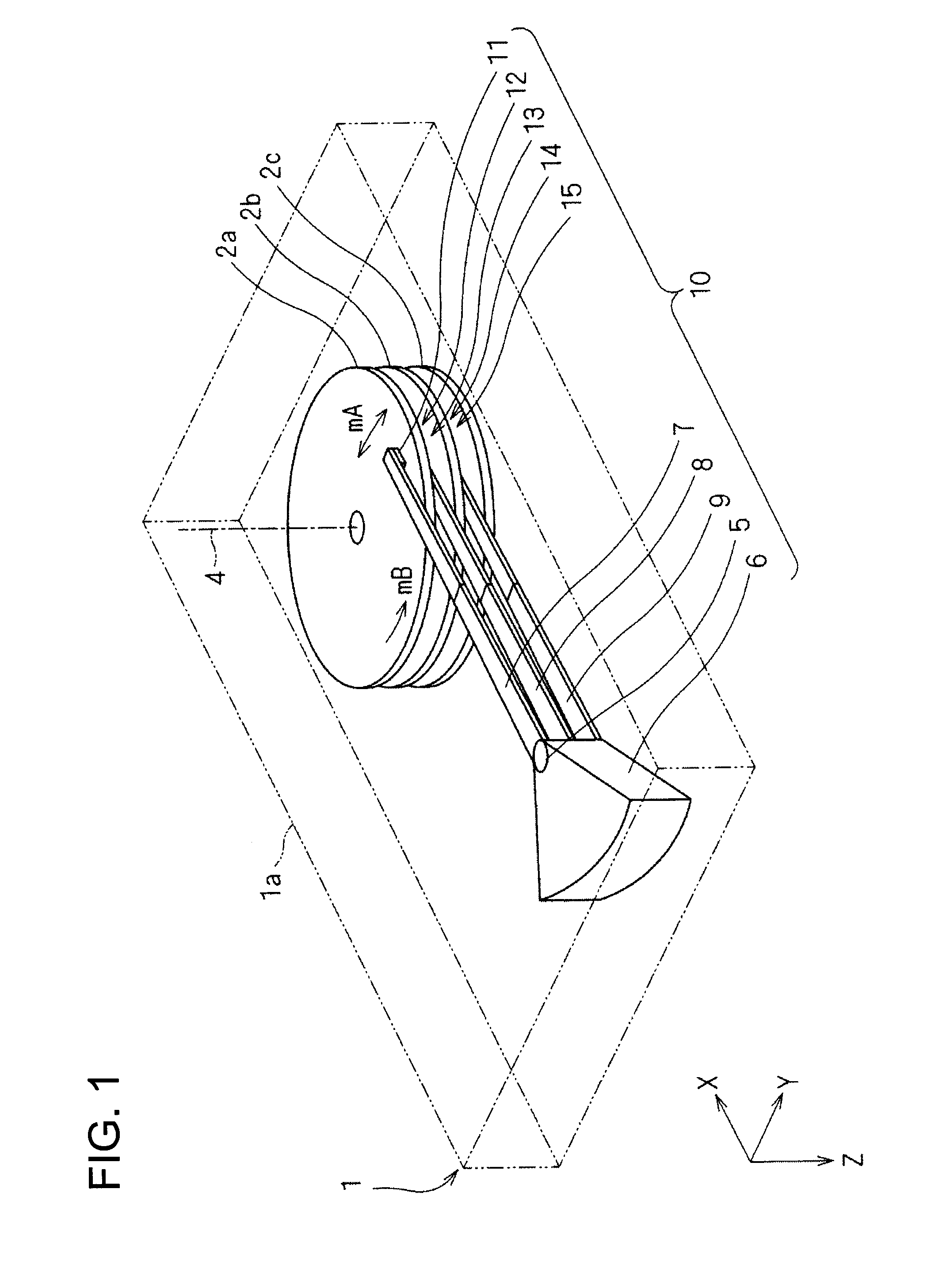
[0080]FIG. 1 shows a schematic diagram indicating a perspective view of an exemplified structural configuration of a light-assisted magnetic recording apparatus 1 embodied in the present invention. The light-assisted magnetic recording apparatus 1 serves as a magnetic information recording apparatus employing the thermal assisting method, and is available as the HDD (Hard Disc Drive), so to speak. Further, a high coercivity material is employed for the recording medium to be incorporated in the light-assisted magnetic recording apparatus 1.

[0081]In this connection, when magnetic information recorded onto the high coercivity material is to be rewritten, in the light-assisted magnetic recording apparatus 1, light is irradiated onto a local area within the recording surface of the high coercivity material, so as to give a...


PUM


Abstract

Disclosed is a near field light generator, which makes it possible to generate the near field light in a preferable way. The generator includes: an optical waveguide having a clad, and a core, which is enclosed by the clad, and a refractive index of which is higher than that of the clad; a metal structural body that is shaped in substantially a plain plate, disposed at a position between the clad and the core; and a low refractive layer that is sandwiched between a partial surface of the core and the metal structural body. The electric field component of the light oscillates within an oscillation surface being substantially perpendicular to the partial surface. The width of the metal structural body in a direction substantially perpendicular to the oscillation surface tapers from the light coupling section of the optical waveguide towards the light emitting section of the optical waveguide.

Description

FIELD OF THE INVENTION[0001]The present invention relates to a near field light generator, and relates to a light assisted magnetic recording head and a light assisted magnetic recording apparatus, each of which employs the near field light generator.TECHNICAL BACKGROUND[0002]Conventionally, widely-known is the light-assisted magnetic information recording technology using the near field light serving as the non-propagation light (for instance, set forth in Patent Documents 1 and 2).[0003]In this connection, according to the light-assisted magnetic information recording technology, a material having a high coercive force (hereinafter, referred to as a high coercivity material, for simplicity) is employed as the recording material, in order to improve the recording density thereof. This kind of the high coercivity material serves as such a recording material that exhibits both a high density recording capability and the thermal stability, and makes it possible to retain magnetized in...

Claims


Application Information

Patent Timeline
IPC IPC(8): G02B6/26
CPCG02B6/3624G02B6/4214G02B2006/12195G11B5/314G02B6/1228G11B7/122G11B7/1387G11B2005/0021G02B6/12002G11B5/6088
Inventor OSAWA, KOU
Owner KONICA MINOLTA INC
Why Eureka
Try Eureka